Honeywell DCS System

BENTLY NEVADA

Home Brands BENTLY NEVADA

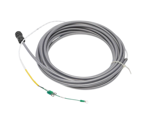
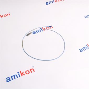
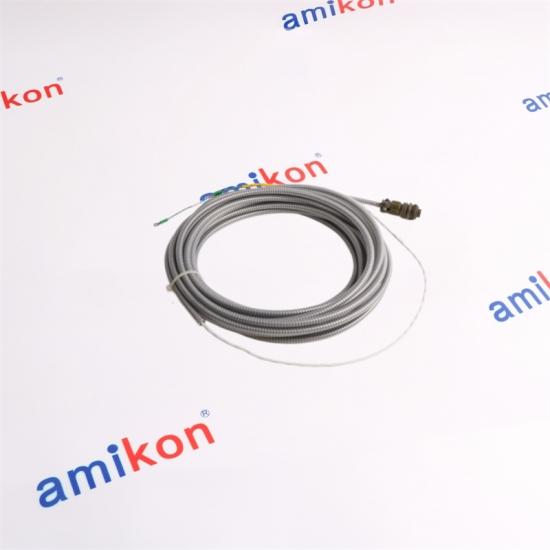
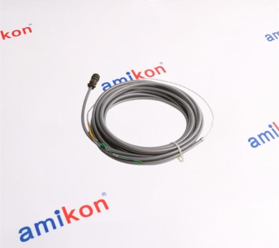
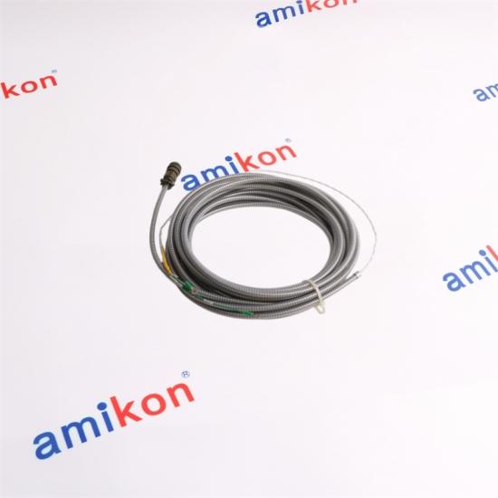
BENTLY NEVADA 84510-30 Approx. 30 FT ARMORED INTERCONNECT CABLE

BENTLY NEVADA 84510-30 Approx. 30 FT ARMORED INTERCONNECT CABLE

BENTLY NEVADA · 84510-NN
84510-30
 
CABLE FAMILY
84510-NN
END CONNECTIONS
2-Socket + Lugs
CONDUCTORS
2-Wire
MECHANICAL PROTECTION
Armored
Designed for connecting compatible Seismoprobe velocity transducers with monitoring equipment.
Our service is more abundant
Welcome to Inquiry
 
Keep critical machinery running with confidence.
SEISMOPROBE VELOCITY TRANSDUCER ACCESSORY
84510-30
 
30 FT ARMORED INTERCONNECT CABLE
A two-wire shielded armored cable configuration designed for connecting compatible Seismoprobe velocity transducers with monitoring equipment.
30 ft
Approx. 9.0 m
22 AWG
0.5 mm² conductors
2-Wire
Shielded construction
CABLE ARCHITECTURE
9200 / 74712
Seismoprobe Velocity Transducers
01 / PRODUCT STRUCTURE
A protected signal route for vibration monitoring
CONDUCTORS
2-Wire
Twisted, shielded 22 AWG conductors provide the signal path between the transducer and receiving equipment.
MECHANICAL PROTECTION
Armored
The armored construction is intended for industrial cable routing where additional mechanical protection is required.
END CONNECTIONS
2-Socket + Lugs
Female connector at the transducer end and terminal lugs at the receiving end.
02 / TECHNICAL PROFILE
84510-30 configuration
Part Number 84510-30
Cable Family 84510-NN
Configured Length 30 ft / approximately 9.0 m
Cable Construction 2-wire shielded armored cable
Conductor 22 AWG / 0.5 mm²
Transducer End 2-socket female connector
Receiving End Terminal lugs
Ordering Range 3 ft to 70 ft / approximately 0.9 m to 21 m
03 / SIGNAL PATH
From machine casing to monitoring equipment
MACHINE
Bearing housing / casing
9200
Velocity transducer
84510-30
Armored signal cable
MONITOR
Monitoring / acquisition equipment
 
The Seismoprobe system measures absolute bearing-housing, casing or structural vibration. The cable provides the electrical path between the compatible velocity transducer and the receiving monitoring equipment.
04 / APPLICATION & FAILURE SCENARIOS
Where 84510-30 becomes a critical replacement
01
Continuous Machinery Monitoring
The cable is used as part of a two-wire Seismoprobe arrangement for measuring casing, bearing-housing or structural vibration.
02
When the Signal Path Is Suspect
A damaged armored run, compromised connector or wiring fault can interrupt the vibration channel and trigger troubleshooting during machinery operation.
03
Downtime Risk
Loss of a required vibration channel can reduce the monitoring coverage available to operators and maintenance teams, increasing the urgency of a correctly matched replacement.
MATCH BEFORE REPLACEMENT
Confirm the complete 84510-30 designation, the connected Seismoprobe type, cable route, connector condition and receiving terminals before replacing a field-installed cable.
05 / ENGINEERED DETAILS
Small cable. Critical measurement path.
Armored routing
The armored construction adds mechanical protection along the installed cable route while preserving the shielded two-conductor signal path.
Defined cable length
The “30” in 84510-30 identifies the 30-foot cable configuration, allowing the replacement length to be matched directly to the installed routing requirement.
Shielded signal conductors
Two 22 AWG shielded conductors form the electrical connection between the velocity transducer and receiving equipment.
Field termination
The female two-socket connector mates with the transducer side, while terminal lugs provide the receiving-end termination.
06 / PURCHASE FAQ
Five questions worth checking before purchase
Why is the exact “-30” suffix important when replacing the cable?
Because the suffix defines the configured cable length. 84510-30 is the 30 ft version, so selecting another length can create an installation mismatch even when the cable family and connector arrangement appear similar.
Which transducers should be checked against 84510-30?
The 84510 cable family is specified with the 9200 and 74712 Seismoprobe Velocity Transducer systems. The connected sensor and receiving channel should still be matched before replacement.
What should be checked if the monitoring channel suddenly becomes unreliable?
Inspect the armored route, connector seating, terminal-lug termination and conductor continuity. A cable fault can interrupt the signal path even when the Seismoprobe itself remains functional.
Is a visually similar 22 AWG cable an acceptable substitute?
Not automatically. The complete construction, armor, connector arrangement, termination, cable length and compatibility with the installed Seismoprobe system should all match the required configuration.
What should I provide when requesting a replacement quotation?
Provide the exact Part Number, Quantity, Destination, Required Date and Machine/System. For this cable, adding the connected transducer model and photographs of both cable ends can make configuration matching faster.
07 / SERVICE ADVANTAGE
More support around every order
Team
GLOBAL SUPPORT TEAM
Warehouse
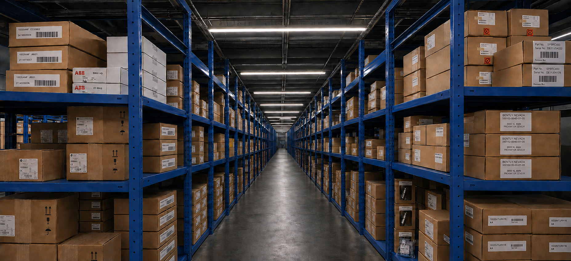
WAREHOUSE OPERATIONS
Customer cooperation
CUSTOMER CONNECTIONS
Service designed around real orders
A multilingual support team, structured order tracking and responsive customer communication help keep the purchasing process clear from quotation to dispatch.
A broader automation supply network
We continue improving our industrial automation supply capability so customers can locate difficult-to-source components and keep critical equipment moving.
08 / ORDER TERMS
DELIVERY
3–5 Days
WARRANTY
12 Months
CONDITION
Brand New
PAYMENT
T/T
DELIVERY WAY
E-packing / FedEx / EMS / TNT / DHL / UPS
09 / AFTER-SALES
Return & Replacement
01
7-Day Contact Window
Please contact us within 7 days after receipt if any issue requires attention.
02
Original Condition
Returned items should remain in their original condition and include the specific reason for the return.
03
Return Freight
The buyer is responsible for shipping costs associated with the return.
READY FOR YOUR NEXT REPLACEMENT?
Send the exact part number.
We will handle the next step.
For quotation, please provide: Part Number · Quantity · Destination · Required Date · Machine/System
Our goal is simple: connect customers with the right automation parts, respond quickly, and reduce the time critical equipment remains unavailable.
DIRECT SALES CONTACT
Miya zheng
PHONE / WHATSAPP
86-18020776792
Fast communication for model matching, quotation and order coordination.

Related Industrial Components

5210003-00A  PPBE0631 P1900520031 AIP171-S1 MSC445-010-00-A
KSS2-GW-MOD PXC36.1-ED TVG430  HBW4GR1V 
200150-09-CN 2017531-001 RB-DA6 CRS60 6749
03144-1033-3103  84661-34   MS-RA770  1SAP140200R0100
ISMA-B-AAC20 PN-250B 51202329-202 OR-42-4K22
VEP1485  TPMC-4SM-BS XL1000C500 FC-SDO-0824
P01120947 - F407 PUV-1530TX 6155F-NPSTRDC FG1015-100
S570-00701PA DO-523-A2  X-NPMI SDO-0824 
BENTLY NEVADA · 84510-30 · SEISMOPROBE INTERCONNECT CABLE Precision connection · Protected routing · Reliable monitoring
Leave A Message
If you are interested in our products and want to know more details,please leave a message here,we will reply you as soon as we can.
Submit

Related Products

Bently Nevada 3500/22M 138607-01 Transient Data Interface Module

The 3500/22M 138607-01 Transient Data Interface (TDI)   is the interface between the 3500 monitoring system and   compatible software (System 1 Condition Monitoring   and Diagnostic software and 3500 System Configuration   software). The TDI combines the function of a 3500/20   Rack Interface Module (RIM) with the data collection   capability of a communication processor such as TDXnet.

Bently Nevada 3500/22M 288055-01 Transient Data Interface

3500/22M is a Transient Data Interface Module manufactured and designed by Bently Nevada as part of the 3500 Series used for monitoring seismic activity. The 3500/22M Transient Data Interface (TDI) is the interface between the 3500 monitoring system and compatible software (System 1 Condition Monitoring and Diagnostic software and 3500 System Configuration software). The TDI combines the function of a 3500/20 Rack Interface Module (RIM) with the data collection capability of a communication processor such as TDXnet.

Bently Nevada 3500/33 149986-01 16-Channel Relay Module

The 3500/33 16-Channel Relay Module is a full-height module   that provides 16 relay outputs. You can place any number of   16-channel relay modules in any of the slots to the right of the   Transient Data Interface (TDI) Module.   Each output of the 3500/33 16-Channel Relay Module can be   independently programmed to perform voting logic.

Bently Nevada 3500/60 163179-01 Temperature Monitor Module

The 3500/60 & 61 modules provide six channels of   temperature monitoring and accept both Resistance   Temperature Detector (RTD) and Thermocouple (TC)   temperature inputs.  The modules condition these inputs and   compare them against user-programmable alarm setpoints.    The 3500/60 and 3500/61 provide identical functionality   except that the 3500/61 provides recorder outputs for each of   its six channels while the 3500/60 does not.

Bently Nevada 3500/60 133811-01 Temperature Monitor Module

The 3500/60 & 61 modules provide six channels of   temperature monitoring and accept both Resistance   Temperature Detector (RTD) and Thermocouple (TC)   temperature inputs.  The 3500/60 133811-01 modules condition   these inputs and compare them against user-programmable alarm setpoints.    The 3500/60 and 3500/61 provide identical functionality   except that the 3500/61 provides recorder outputs for each of   its six channels while the 3500/60 does not.

Bently Nevada 3500/72M 176449-08 Recip Rod Position Monitor

The 3500/72M Recip Rod Position Monitor meets API 618   requirements for reciprocating compressors. It measures:   l Rod position   l Rod drop   l Hyper-compressor   The four-channel 3500/72M Recip Rod Position Monitor   accepts input from proximity transducers, conditions the   signal to provide dynamic and static position measurements,   and compares the conditioned signals with userprogrammable alarms.   Each channel, depending on how you configure it, typically   conditions its input signal to generate various parameters   called measured values.

Bently Nevada 3500/62 163179-03 Process Variable Monitor

The 3500/62 Process Variable Monitor is a 6-channel monitor   for processing machine critical parameters that merit   continuous monitoring, such as pressures, flows,   temperatures, and levels. The monitor accepts +4 to +20 mA   current inputs or any proportional voltage inputs between -10   Vdc and +10 Vdc. It conditions these signals and compares   the conditioned signals to user-programmable alarm   setpoints. 

Bently Nevada 3500/62 133811-03 Process Variable Monitor

The 3500/62 Process Variable Monitor is a 6-channel monitor   for processing machine critical parameters that merit   continuous monitoring, such as pressures, flows,   temperatures, and levels. The monitor accepts +4 to +20 mA   current inputs or any proportional voltage inputs between -10   Vdc and +10 Vdc. It conditions these signals and compares   the conditioned signals to user-programmable alarm   setpoints. 

Quality | Reliability | Integrity

More than 40.000.000 products available and worldwide support

Leave A Message
If you are interested in our products and want to know more details,please leave a message here,we will reply you as soon as we can.
Submit

Home

Products

whatsApp

contact