Honeywell DCS System

BENTLY NEVADA

Home Brands BENTLY NEVADA

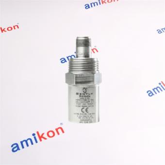
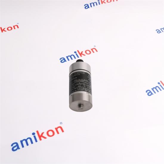
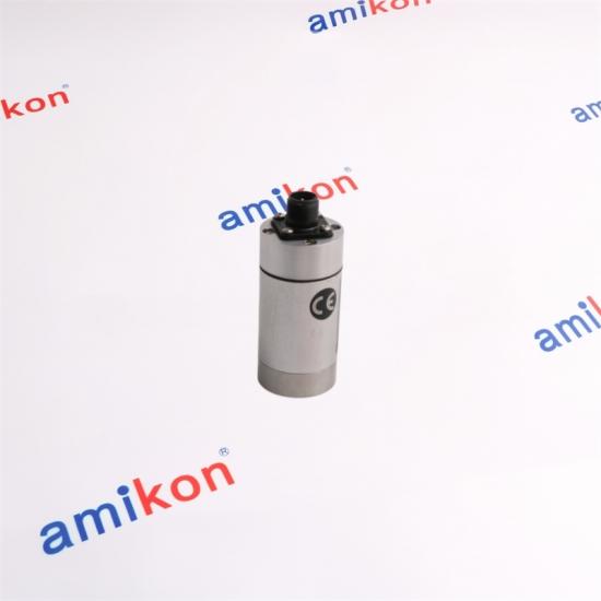
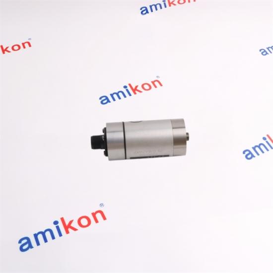
BENTLY NEVADA 9200-06-01-11-04 Two-wire moving-coil velocity transducer

BENTLY NEVADA 9200-06-01-11-04 Two-wire moving-coil velocity transducer

BENTLY NEVADA
 
VIBRATION MONITORING
9200-06-01-11-04
 
KEY PARAMETERS
9200 Series Monitoring
01
PRODUCT FAMILY
9200 Series
02
MONITORING ROLE
Vibration Protection
03
APPLICATION
Rotating Machinery
 
AUTOMATION PARTS
Supply That
Keeps Industry Moving.
SALES MANAGER
Miya zheng
CONTACT
QUICK RESPONSE
SEISMOPROBE VELOCITY TRANSDUCER

9200-06-01-11-04


Two-wire moving-coil velocity transducer for absolute bearing-housing, casing and structural vibration measurement, configured for a 10 Hz minimum operating frequency with an isolated M10 × 1 mounting base.

20
mV/mm/s sensitivity
10
Hz minimum frequency
50
g shock resistance
ORDER CONFIGURATION
9200 / 06 / 01 / 11 / 04
Mounting angle 0° ±100°
Minimum frequency 10 Hz
Connector Top mount
Mounting base Isolated M10 × 1
Approval ATEX / IECEx
CONFIGURATION LOGIC
Every suffix has a mechanical or operating purpose.

The complete ordering code is important when replacing an installed transducer because orientation, minimum operating frequency, connector position, electrical isolation and hazardous-area approval are all part of the selected configuration.

06
0° ±100°
10 Hz
01
Top mount
No cable
11
Isolated circular
M10 × 1
04
ATEX / IECEx
ISOLATED BASE
The isolated circular M10 × 1 mounting base is particularly important for this configuration. The 9200 ordering rules require an isolated base when the 04 agency approval option is selected.
TOP-MOUNT CONNECTION
Option 01 is a top-mounted connector without integral cable. The installation therefore uses an appropriate interconnect cable between the transducer and the monitoring or test equipment.
TECHNICAL PERFORMANCE
9200 Seismoprobe Characteristics
Sensitivity 20 mV/mm/s
Tolerance ±5%
Frequency response 10–1000 Hz
Response tolerance +0 / −3 dB typical
Velocity range 25 mm/s
Dynamic displacement 2.54 mm peak-to-peak
Temperature −29 to +121°C
Coil resistance 1.25 kΩ ±5%
Coil inductance 125 mH typical
Shock resistance 50 g peak
Humidity Up to 95% noncondensing
Maximum altitude 2000 m
01 / SENSOR
Moving-Coil Technology

The 9200 generates a voltage directly proportional to vibration velocity. Its two-wire, self-powered arrangement eliminates the need for external power at the transducer.

02 / MECHANICAL
Compact Casing

The typical 9200 body is approximately 102 mm high and 41 mm in diameter. The case and adapter use anodized aluminum A204, while the 9200 gasket is neoprene.

03 / SIGNAL PATH
Direct Velocity Output

The output is taken across pins A and B. Pin A becomes positive relative to pin B when case velocity is directed toward the connector.

MACHINE CONDITION MONITORING
Where the 9200 becomes a critical measurement point

The Seismoprobe system measures absolute vibration at bearing housings, machine casings and structural mounting locations. It is useful when the vibration reaching the casing needs to be monitored as a machine condition signal.

Rotating Equipment

Bearing housings, machine casings and structural locations can carry vibration generated by the rotating machine.

Unbalance / Misalignment

Rotor unbalance and misalignment can produce changes in rotor vibration that become visible through an appropriately installed casing measurement.

Replacement Search

When a monitoring channel suddenly becomes unavailable, engineers often search the complete part number because mounting angle, cable arrangement, isolation and approval requirements must match.

WHY INSTALLATION QUALITY MATTERS
The transducer should be mounted where sufficient rotor vibration is transmitted to the casing or bearing housing. Poor installation can reduce amplitude or frequency response and can create signals that do not represent actual machine vibration. For a protection application, that can mean delayed recognition of a developing machinery condition or an unreliable measurement channel.
SYSTEM CONNECTION
9200 + Interconnect + Monitoring Equipment
01
9200 Transducer

Two-wire moving-coil sensing element producing a voltage proportional to vibration velocity.

02
Interconnect Cable

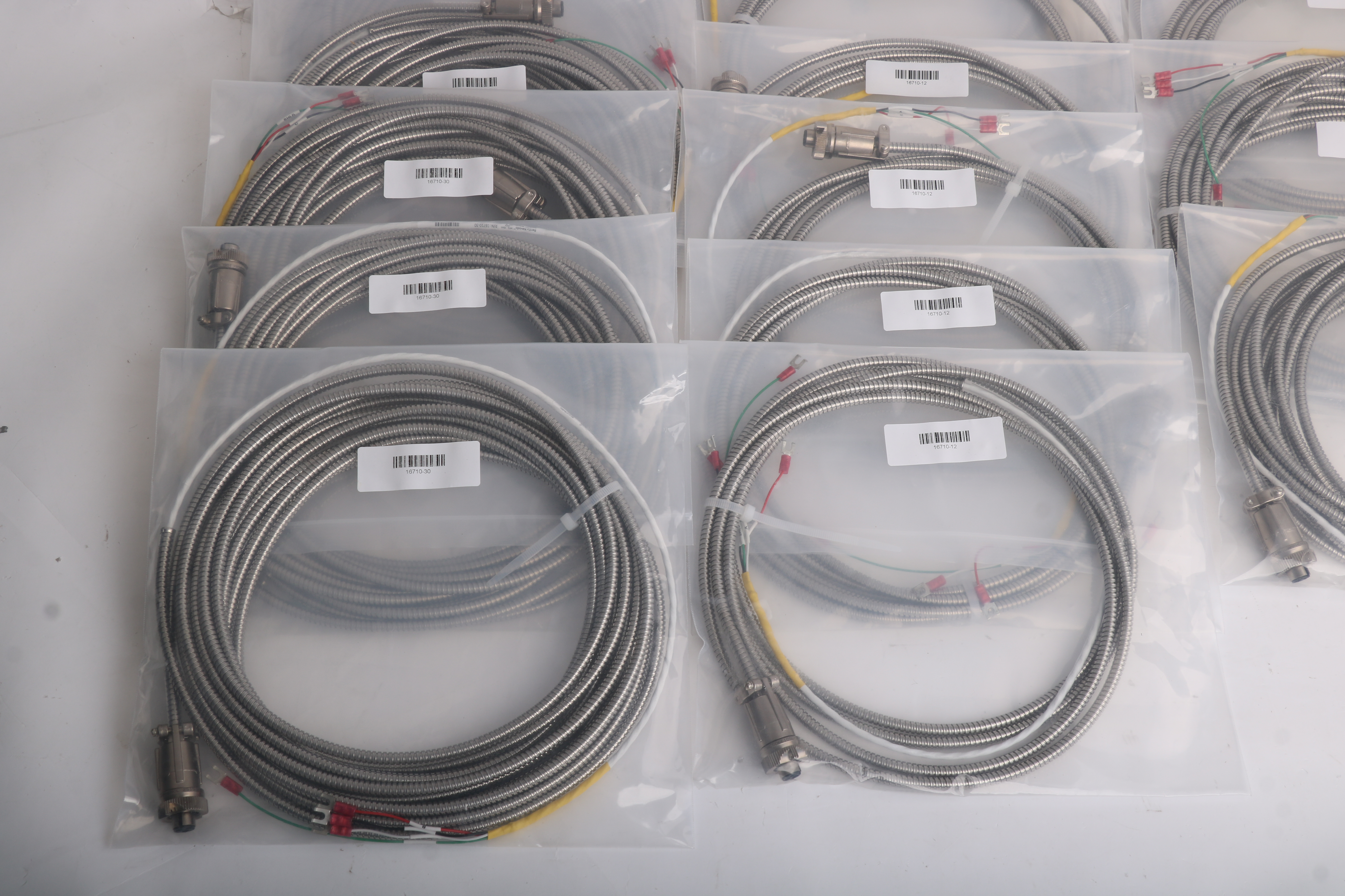
Option 01 has no integral cable, so a compatible two-wire cable is used between the transducer and the receiving instrument.

03
Monitor / Tester

The 9200 can support continuous monitoring or periodic measurements with suitable test and diagnostic equipment.

GLOBAL AUTOMATION PARTS SUPPORT
A service experience built around difficult-to-source parts

We combine multilingual support, structured order tracking and customer relationship management to make communication easier from quotation through delivery. Our team continues to improve the way industrial automation parts are supplied across international markets.

Professional automation team
Multilingual Support Team
Automation parts warehouse
Organized Warehouse Operations
Customer cooperation
Worldwide Customer Cooperation
MULTILINGUAL SUPPORT
Clear communication for international customers and engineering teams.
ORDER TRACKING
Customized order coordination helps maintain visibility throughout the purchasing process.
NO HIDDEN HANDLING CHARGES
Straightforward commercial communication without additional handling fees.
QUOTATION REQUEST
Five details speed up the quotation

Please provide these details when requesting the 9200-06-01-11-04:

01 Part Number
02 Quantity
03 Destination
04 Required Date
05 Machine / System
ORDER TERMS
Delivery 3–5 Business Days
Warranty 12 Months
Condition Brand New
Delivery Way E-packing / FedEx / EMS / TNT / DHL / UPS
Payment Term T/T
PURCHASING FAQ
Questions worth checking before replacement
01. Why should the replacement match 9200-06-01-11-04 rather than simply another 9200?
The 9200 family has several mounting-angle, frequency, connector, base and approval combinations. This exact configuration specifies a 10 Hz minimum operating frequency, top-mounted connector, isolated M10 × 1 base and ATEX/IECEx approval. A different 9200 code can therefore change the installed arrangement even though the sensor family is the same.
02. Is the “11” suffix simply a different M10 × 1 mounting thread?
No. The 11 option identifies an isolated circular M10 × 1 mounting base. The isolation is significant because the 04 ATEX/IECEx agency option requires an isolated base. Matching only the M10 × 1 mechanical size would not reproduce the complete configuration.
03. Why does this model use a 10 Hz minimum operating frequency?
The 06 mounting-angle/frequency option specifies 0° ±100° and a 10 Hz minimum operating frequency. This makes the configuration different from 9200 variants using the 4.5 Hz or 15 Hz minimum-frequency options, so the suffix should be matched when replacing an installed unit.
04. What should be checked if a replacement sensor gives an unexpectedly low vibration signal?
Check the mounting location, mechanical coupling and orientation before assuming the transducer itself has failed. The casing measurement must receive sufficient rotor vibration. Improper installation can reduce amplitude or frequency response and may create signals that do not represent actual machine vibration.
05. Does the 01 connector option include the cable required to reach the monitor?
No. Option 01 is a top-mounted connector with no integral cable. An appropriate two-wire interconnect cable is selected separately. Depending on the installation, available cable choices include shielded and armored constructions and different lengths.
AFTER RECEIPT
Return / Replacement

If an issue occurs after delivery, please contact us within 7 days. Returned items should remain in original condition, with the reason for return clearly provided. Once the returned item is received, we will arrange the applicable return or replacement solution.

RETURN SHIPPING
Shipping Cost

Shipping costs generated by a return are the buyer's responsibility. Please confirm the return arrangement with our team before sending the item back.

9200-06-01-11-04
Keep the right vibration channel running.

Send the complete part number, quantity, destination, required date and machine/system so our team can prepare a precise quotation.

DIRECT CONTACT
Sales Manager
Miya zheng
RELATED AUTOMATION PARTS
Additional models
SNB10D-245
AAI135-H00
TPPLMAROC
2711PRDT10C
68-6211
AM-T-960
AFD4
BK Precision 4051
2711p-rp8d/A
MB-AO-TR-380X-118268
SGDH-05DE-OY
MC206X P136
MDM40TF1D2AXXIX
M0320
NFPW444 NFPW444-10
1771-0FE2/B
2711P-RP8D
6SL3130-6AE21-0AB1
VB00761F-CF
BSSBLU32
FW-28
21000-34-05-00-015-04-02
25B-D4P0N104
IC670MDL642
6ES7521-1BH10-0AA0
3HAC055697-003
3HAC049969-001
IC660HHM500
IC660BBA103
IC754CSF06CTD
CC-PDIL01
25A-D6P0N104
Leave A Message
If you are interested in our products and want to know more details,please leave a message here,we will reply you as soon as we can.
Submit

Related Products

Bently Nevada 3500/22M 138607-01 Transient Data Interface Module

The 3500/22M 138607-01 Transient Data Interface (TDI)   is the interface between the 3500 monitoring system and   compatible software (System 1 Condition Monitoring   and Diagnostic software and 3500 System Configuration   software). The TDI combines the function of a 3500/20   Rack Interface Module (RIM) with the data collection   capability of a communication processor such as TDXnet.

Bently Nevada 3500/22M 288055-01 Transient Data Interface

3500/22M is a Transient Data Interface Module manufactured and designed by Bently Nevada as part of the 3500 Series used for monitoring seismic activity. The 3500/22M Transient Data Interface (TDI) is the interface between the 3500 monitoring system and compatible software (System 1 Condition Monitoring and Diagnostic software and 3500 System Configuration software). The TDI combines the function of a 3500/20 Rack Interface Module (RIM) with the data collection capability of a communication processor such as TDXnet.

Bently Nevada 3500/33 149986-01 16-Channel Relay Module

The 3500/33 16-Channel Relay Module is a full-height module   that provides 16 relay outputs. You can place any number of   16-channel relay modules in any of the slots to the right of the   Transient Data Interface (TDI) Module.   Each output of the 3500/33 16-Channel Relay Module can be   independently programmed to perform voting logic.

Bently Nevada 3500/60 163179-01 Temperature Monitor Module

The 3500/60 & 61 modules provide six channels of   temperature monitoring and accept both Resistance   Temperature Detector (RTD) and Thermocouple (TC)   temperature inputs.  The modules condition these inputs and   compare them against user-programmable alarm setpoints.    The 3500/60 and 3500/61 provide identical functionality   except that the 3500/61 provides recorder outputs for each of   its six channels while the 3500/60 does not.

Bently Nevada 3500/60 133811-01 Temperature Monitor Module

The 3500/60 & 61 modules provide six channels of   temperature monitoring and accept both Resistance   Temperature Detector (RTD) and Thermocouple (TC)   temperature inputs.  The 3500/60 133811-01 modules condition   these inputs and compare them against user-programmable alarm setpoints.    The 3500/60 and 3500/61 provide identical functionality   except that the 3500/61 provides recorder outputs for each of   its six channels while the 3500/60 does not.

Bently Nevada 3500/72M 176449-08 Recip Rod Position Monitor

The 3500/72M Recip Rod Position Monitor meets API 618   requirements for reciprocating compressors. It measures:   l Rod position   l Rod drop   l Hyper-compressor   The four-channel 3500/72M Recip Rod Position Monitor   accepts input from proximity transducers, conditions the   signal to provide dynamic and static position measurements,   and compares the conditioned signals with userprogrammable alarms.   Each channel, depending on how you configure it, typically   conditions its input signal to generate various parameters   called measured values.

Bently Nevada 3500/62 163179-03 Process Variable Monitor

The 3500/62 Process Variable Monitor is a 6-channel monitor   for processing machine critical parameters that merit   continuous monitoring, such as pressures, flows,   temperatures, and levels. The monitor accepts +4 to +20 mA   current inputs or any proportional voltage inputs between -10   Vdc and +10 Vdc. It conditions these signals and compares   the conditioned signals to user-programmable alarm   setpoints. 

Bently Nevada 3500/62 133811-03 Process Variable Monitor

The 3500/62 Process Variable Monitor is a 6-channel monitor   for processing machine critical parameters that merit   continuous monitoring, such as pressures, flows,   temperatures, and levels. The monitor accepts +4 to +20 mA   current inputs or any proportional voltage inputs between -10   Vdc and +10 Vdc. It conditions these signals and compares   the conditioned signals to user-programmable alarm   setpoints. 

Quality | Reliability | Integrity

More than 40.000.000 products available and worldwide support

Leave A Message
If you are interested in our products and want to know more details,please leave a message here,we will reply you as soon as we can.
Submit

Home

Products

whatsApp

contact