

|
BENTLY NEVADA / ACCELEROMETER ACCESSORIES
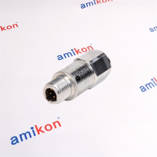
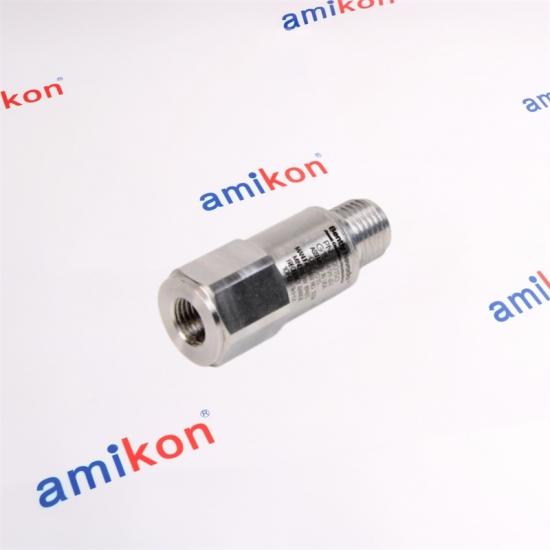
200151-20-03-00Accelerometer Interface Standard CableA 2.0 meter interface cable configuration for the 20015x accelerometer family, specified with a blue armored cable and standard coupling nuts at both ends.
|
PART CONFIGURATION
200151 / 20 / 03 / 00
01 — CABLE LENGTH
20 = 2.0 meters
02 — ARMOR OPTION
03 = Blue cable with armor
03 — COUPLING NUT
00 = Standard coupling nut
|
Key configuration and cable characteristics for the 200151 interface family.
| Model | 200151-20-03-00 |
| Product designation | Accelerometer Interface Standard Cable |
| Cable length | 2.0 meters |
| Armor option | Blue cable with armor |
| Coupling nut | Standard coupling nut |
| Conductors | 4-conductor, 22 AWG |
| Shield | Braided shield with drain wire, 85% minimum coverage |
| Outer jacket | PVC |
| Connector arrangement | Connectors on both ends |
| Connector seal | IP67 seal to transducers and mating hardware |
| Cable operating temperature | -20°C to +100°C (-4°F to +212°F) |
| Minimum bend radius | 63.5 mm (2.5 in) |
| Maximum cable length | 25 m (82 ft) |
|
01 / SIGNAL PATH
Stable sensor connectionThe cable provides the connection between the accelerometer and associated monitoring hardware within the 20015x measurement arrangement. |
02 / MECHANICAL PROTECTION
Armored configurationThe -03 configuration specifies a blue cable with armor, providing a mechanically protected cable arrangement for industrial installation. |
03 / ENVIRONMENT
Sealed connectionsThe cable connectors provide an IP67 seal to the transducer and mating hardware, with molded connections and additional moisture protection. |
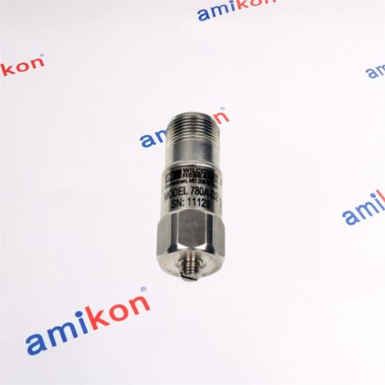
20015x Accelerometer SystemsThe 20015x accelerometers are general-purpose, wide-frequency, case-mounted seismic transducers designed for use with Trendmaster ProTIMs. The 200150 accelerometer can also operate with the Trendmaster 2000 system. The associated measurement arrangement can interface with the 200100 Dual Acceleration-to-Velocity flexiTIM Module, the 89130-01 Acceleration-to-Velocity TIM, and 1900/25 and 1900/27 monitors. |
Why the Cable MattersWhen an accelerometer cable becomes damaged, incorrectly connected, excessively bent, or otherwise unsuitable for the installation, the vibration measurement path can become unreliable. For condition monitoring, that can affect the ability of the monitoring arrangement to represent actual machine vibration. The 20015x accelerometer family is used for casing and bearing-housing measurements. Typical machine conditions such as unbalance and misalignment can produce changes in rotor vibration that are transmitted to the machine casing. |
|
01
Machine casing
|
02
Accelerometer
|
03
Interface cable
|
04
Monitoring hardware
|
|
MAINTENANCE SCENARIO
When a Cable Replacement Becomes CriticalA replacement search for 200151-20-03-00 is particularly relevant when maintenance teams need to restore the signal path between a 20015x accelerometer and its monitoring arrangement while keeping the existing installation configuration. |
|
|||||||||
The complete ordering pattern for this cable configuration.
| Model | 200151 | Accelerometer Interface Standard Cable, connectors on both ends |
| Length | 20 | 2.0 meters |
| Armor | 03 | Blue cable with armor |
| Coupling nut | 00 | Standard coupling nut |
|
PRICE & AVAILABILITY
Need a Price for 200151-20-03-00?For a fast quotation, send the part number together with the quantity and installation requirements. This helps us confirm the appropriate commercial offer for your project. PLEASE INCLUDE
Part Number | Quantity | Destination | Required Date | Machine/System |
DIRECT CONTACT
Miya Zheng
Sales Manager
|
|
DELIVERY
3–5 Days
|
WARRANTY
12 Months
|
PACKAGING
Brand New
|
PAYMENT
T/T
|
From quotation to shipment, every order is handled with direct communication and practical support.
 CUSTOMER CONNECTION
Closer communication. Faster decisions.
|
 OUR TEAM
Professional support from inquiry to delivery.
|
Five practical questions before ordering the 200151-20-03-00.
| 01 |
What exactly does 200151-20-03-00 include?It is the 200151 Accelerometer Interface Standard Cable configuration with connectors on both ends. The -20 option specifies 2.0 meters, -03 specifies blue cable with armor, and -00 specifies the standard coupling nut. |
| 02 |
Which accelerometer family is this cable associated with?The 200151 cable belongs to the interface cable range associated with the 200150, 200155 and 200157 accelerometers. |
| 03 |
What should I check before replacing an existing cable?Check the complete part-number configuration, cable length, armor option, coupling-nut option and the existing accelerometer arrangement. The 200151 family uses different length and coupling configurations, so the complete part number matters. |
| 04 |
Can the cable be routed with a tight bend?The specified minimum bend radius for 200151 is 63.5 mm (2.5 inches). Installation should maintain this limit, particularly when routing the cable around machine housings or other fixed structures. |
| 05 |
What happens if the wrong 20015x cable configuration is ordered?A mismatch in length, coupling arrangement or installation configuration can make replacement work more difficult and may delay restoration of the intended vibration measurement path. For procurement, compare the complete part number rather than only the 200151 base number. |
| FMH2A09TR-EN43EZ | UTD2102E | SM87PBLAUL3BOYGHRZ | XNV-L6080RA |
| MS4609F1210 | S2BN1D-19030 | T266-DC-15 | XRE2024D |
| 51202329-202 | 03144-1033-3103 | BKDR-16 | F3502 |
| 10B-PCTA | GE DT3025 | COG120 | HV21 SV40 |
| AIP-0800-002-001 | 2010105S811 | ABB PM861AK01 3BSE018157R1 | 51202329-402 |
| ST-CE1075-2-U100-B | ADV159-P00 | SL2500 | MA-63 |
| AAM11-S2 | FTD-2000 | MX-M15D-SEC-DNIGHT-D51N51 | 00322513-02 |
| OKP0N34 | BVME795 | FGE100X | 835140-1 |
|
QUICK PRICE CHECK
Comparing Models or Building a Spare-Parts Order?Send your required models together with quantity, destination, required date and machine/system. We can prepare a concise quotation for your purchasing decision. |
Request Pricing |
|
A BROADER WAY TO SUPPORT YOUR PROCUREMENT
Our Service Is More Abundant.Excellent service runs through every process of our operation. In addition, we invest in global talent and dedicated technology to provide customers with more responsive and professional service.
|
 More Parts. More Choices. More Connection.
We continue to improve the global supply of automation parts. Wherever our customers are located, we aim to connect them with the components they need through a broader and more responsive supply network. |
Looking for 200151-20-03-00 or another industrial automation component? Send the exact part number, quantity, destination, required date and machine/system for a direct quotation.
1. Please contact us within 7 days if you have any question after you receiving the items.
2. The returned items has to be in its original condition, specific reason for the return, we will issue a return or replacement for your order after we received the returns.
3. The buyer is responsible for all the shipping cost incurred.
| Sales Manager: Miya Zheng | Email: sales@amikon.cn | Phone / WhatsApp: 86-18020776792 |

The 3500/22M 138607-01 Transient Data Interface (TDI) is the interface between the 3500 monitoring system and compatible software (System 1 Condition Monitoring and Diagnostic software and 3500 System Configuration software). The TDI combines the function of a 3500/20 Rack Interface Module (RIM) with the data collection capability of a communication processor such as TDXnet.

3500/22M is a Transient Data Interface Module manufactured and designed by Bently Nevada as part of the 3500 Series used for monitoring seismic activity. The 3500/22M Transient Data Interface (TDI) is the interface between the 3500 monitoring system and compatible software (System 1 Condition Monitoring and Diagnostic software and 3500 System Configuration software). The TDI combines the function of a 3500/20 Rack Interface Module (RIM) with the data collection capability of a communication processor such as TDXnet.

The 3500/33 16-Channel Relay Module is a full-height module that provides 16 relay outputs. You can place any number of 16-channel relay modules in any of the slots to the right of the Transient Data Interface (TDI) Module. Each output of the 3500/33 16-Channel Relay Module can be independently programmed to perform voting logic.

The 3500/60 & 61 modules provide six channels of temperature monitoring and accept both Resistance Temperature Detector (RTD) and Thermocouple (TC) temperature inputs. The modules condition these inputs and compare them against user-programmable alarm setpoints. The 3500/60 and 3500/61 provide identical functionality except that the 3500/61 provides recorder outputs for each of its six channels while the 3500/60 does not.

The 3500/60 & 61 modules provide six channels of temperature monitoring and accept both Resistance Temperature Detector (RTD) and Thermocouple (TC) temperature inputs. The 3500/60 133811-01 modules condition these inputs and compare them against user-programmable alarm setpoints. The 3500/60 and 3500/61 provide identical functionality except that the 3500/61 provides recorder outputs for each of its six channels while the 3500/60 does not.

The 3500/72M Recip Rod Position Monitor meets API 618 requirements for reciprocating compressors. It measures: l Rod position l Rod drop l Hyper-compressor The four-channel 3500/72M Recip Rod Position Monitor accepts input from proximity transducers, conditions the signal to provide dynamic and static position measurements, and compares the conditioned signals with userprogrammable alarms. Each channel, depending on how you configure it, typically conditions its input signal to generate various parameters called measured values.

The 3500/62 Process Variable Monitor is a 6-channel monitor for processing machine critical parameters that merit continuous monitoring, such as pressures, flows, temperatures, and levels. The monitor accepts +4 to +20 mA current inputs or any proportional voltage inputs between -10 Vdc and +10 Vdc. It conditions these signals and compares the conditioned signals to user-programmable alarm setpoints.

The 3500/62 Process Variable Monitor is a 6-channel monitor for processing machine critical parameters that merit continuous monitoring, such as pressures, flows, temperatures, and levels. The monitor accepts +4 to +20 mA current inputs or any proportional voltage inputs between -10 Vdc and +10 Vdc. It conditions these signals and compares the conditioned signals to user-programmable alarm setpoints.


Inventory Products


More than 40.000.000 products available and worldwide support


 Trust Guaranteed
 Customer Support


 IPv6 network supported