

|
Product Line |
1336 PLUS II Drives |
|
Part Number |
1336F-MCB-SP1F |
|
Weight |
5.00 lbs (2.27 kg) |
|
Description |
Main Control Board |
|
Product Family |
1336 Plus II |

Overview
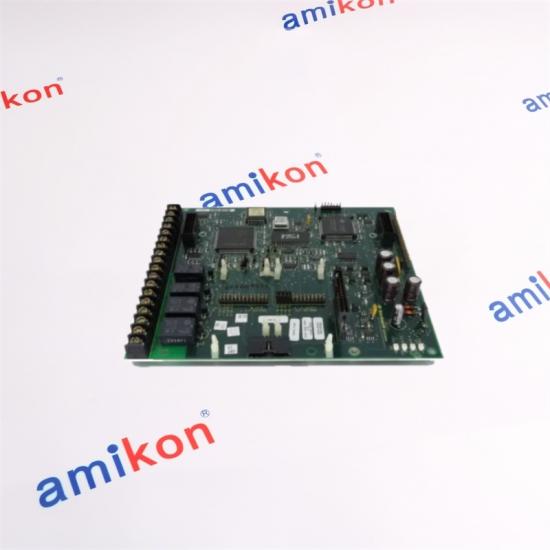
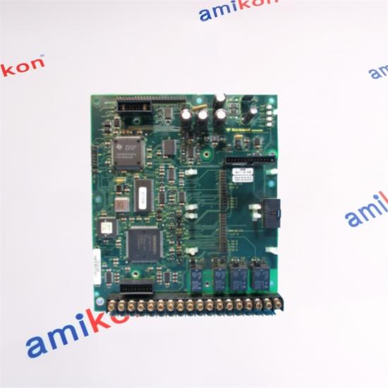
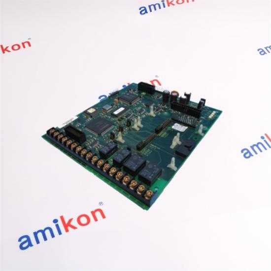
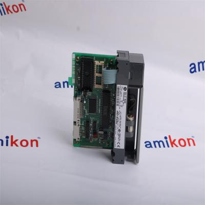
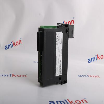
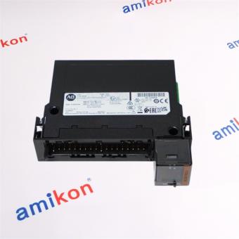
The 1336F-MCB-SP1F is part of the 1336 Plus Adjustable Frequency AC Drive. This is the main inverter control circuit board of a 1336F Plus II drive that is designed for use for frames B-G. It hosts the TB2 terminals which are mainly used for VFD I/O connection. Each 1336F VFD requires the use of a single 1336F-MCB-SP1F. This board is superseded by the 1336F-MCB-SP1M.
Specifications
|
Manufacturer |
Allen Bradley |
|
Product Type |
Main Control Board |
|
Product Line |
1336 PLUS II Drives |
|
Part Number |
1336F-MCB-SP1F |
|
Weight |
5.00 lbs (2.27 kg) |
|
Description |
Main Control Board |
|
Product Family |
1336 Plus II |
|
Input Power |
115 V AC |
|
Product Lifecycle Status* |
Discontinued/Obsolete |
|
Compatible Drives |
Frame B-G |
|
Drive power ratings |
Frame B: 7.5 HP, 10 HP, 15 HP, 20 HP, 25 HP, 30 HP; Frame C: X40HP, 40 HP, 50 HP, X 60 HP; Frame D: 60 HP; 75 HP;100 HP; 125 HP; X150 HP; Frame E: 150 HP, 200 HP, 250 HP; Frame F: 250 HP, 300 HP, 350 HP, 400 HP, 450 HP; Frame G: X250 HP, 300 HP, 350 HP, 400 HP, 450 HP, 500 HP, 600 HP, 650 HP |
|
No. of units per drive |
One (1) |
|
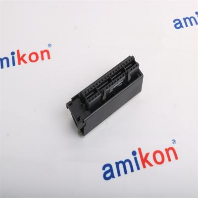
Terminal strip |
TB2 |
|
Appropriate wire size |
Belden 8760 (or equiv.)–0.750 mm2 (18 AWG), twisted pair, shielded; Belden 8770 (or equiv.)–0.750 mm2 (18 AWG), 3 conductor, shielded; Belden 9460 (or equiv.)–0.750 mm2 (18 AWG), twisted pair, shielded |
|
Analog inputs |
0-10K Ohm; 0-10 VDC; 0-20 mA |
|
Analog output |
0-10 VDC; 0-20 mA |
|
Contact output |
CR1, CR2 and CR3 programmable Contacts |
|
Troubleshooting symbol |
MAIN CTL |
|
Superseded by |
1336S-MCB-SP1M |
|
Product Lifecycle |
Discontinued |
Descripution
|
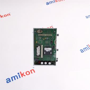
The 1336F-MCB-SP1F is a 1336 Plus II Main Control Board (MCB) that is a replacement unit of an existing, pre-installed assembly that comes with a fully functional 1336 Plus II Adjustable Frequency AC Drive by Allen-Bradley. The 1336F-MCB-SP1F being the main control board, this board hosts a variety of primary interfaces including the Control and Signal Wiring terminal block (TB2) where external I/O signals are terminated; RIO option board; Drive mounted snap-in Human Interface Module (HIM), Internal communications module or Flash interface board; Internal communication adapter. It also hosts the mounting location of the control interface board option card (TB3) and jumper connections points for other PCB cards. The 1336F-MCB-SP1F is designed for use with the 1336 Plus II drive with a frame size of B-G and Horsepower ratings of 7.5 HP, 10 HP, 15 HP, 20 HP, 25 HP, 30 HP for Frame B; X40HP, 40 HP, 50 HP, X 60 HP for Frame C; 60 HP; 75 HP;100 HP; 125 HP; X150 HP for Frame D; 150 HP, 200 HP, 250 HP for Frame E; 250 HP, 300 HP, 350 HP, 400 HP, 450 HP for Frame F and X250 HP, 300 HP, 350 HP, 400 HP, 450 HP, 500 HP for Frame G. When replacing the existing 1336F-MCB-SP1F, it is necessary to completely remove supply power to the drive. Also, allow the drive capacitors to entirely discharge prior to hardware modification. Confirm capacitor charge by measuring with the use of a multimeter. Only when the capacitor has been fully discharging shall the board replacement be initiated. |
|
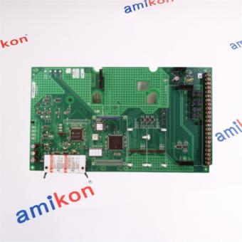
The 1336F-MCB-SP1F PCB Main Control Board by Allen-Bradley is the main control board for the Allen-Bradley 1336 Plus II Frame B to G drives, which houses the control interface boards and other RIO boards. The main control board coordinates all the functions of the drive, and it has various ports for connection to peripheral devices (for example an HIM is connected to the drive-through Port 1 on the main control board) and a drive nameplate is located on the face of the main control board. The 1336F-MCB-SP1F main control board connects to the control interface board using the J2 and J4 jumper connectors located on the lower side of the board and also on the bottom of the main control board is the terminal block (TB2) with 22 positions and with 0.3 mm2 (14 and 22 AWG) wire size. The 1336F-MCB-SP1F is installed by placing the board on the mounting plate and by tightening the 11 screws holding the main control board to the mounting plate with a 26in-lb (3N-m) rating. Various wires from the terminal block (TB2) are connected and ground wires, an 8-pin connector from HIM Mounting Plate, and the J1, J2, J6, and J8 jumper connectors are connected to the main control. Also, wires from the TB3 terminal block are connected and the board has LED indicators that show the status of various connected boards. The HIM cradle is installed on the board with 4 tightening screws, with the control interface board also installed on the main control board, and the communication connector on the J3 connector is also attached. |
FAQ for AB 1336S-MCB-SP1M
|
1. How does the AB 1336S-MCB-SP1M orchestrate real-time control logic and operational governance within Allen-Bradley 1336-series AC drive ecosystems? |
|
The AB 1336S-MCB-SP1M serves as the primary control board responsible for processing drive commands, managing parameter execution, monitoring system status, and coordinating communication between critical drive subsystems. |
|
2. Why is the AB 1336S-MCB-SP1M regarded as a pivotal component for preserving functional integrity in mature variable-frequency drive installations? |
|
The AB 1336S-MCB-SP1M enables the restoration of core control capabilities in aging drives, allowing facilities to maintain production continuity while extending the service life of installed equipment. |
|
3. What performance anomalies could signify that the AB 1336S-MCB-SP1M is experiencing control-board degradation or impending failure? |
|
Indicators may include intermittent fault codes, abnormal startup behavior, communication disruptions, parameter corruption, unexpected drive shutdowns, or inconsistent motor response associated with the AB 1336S-MCB-SP1M. |
|
4. How can the AB 1336S-MCB-SP1M contribute to enhanced operational resilience in high-demand industrial motor control applications? |
|
By providing accurate command processing, stable control execution, and reliable system supervision, the AB 1336S-MCB-SP1M helps maintain process stability and reduces the likelihood of unplanned production interruptions. |
|
5. Which compatibility and engineering criteria should be thoroughly assessed before deploying the AB 1336S-MCB-SP1M as a replacement control module? |
|
Engineers should evaluate drive family compatibility, firmware alignment, board revision specifications, installation requirements, and application-specific operating parameters to ensure successful integration of the AB 1336S-MCB-SP1M. |
Contact Us
We are the ideological leader of the world's automation manufacturing industry and are committed to promoting global industry exchanges. No matter how complex your problem is, our experienced professional team will use the industry knowledge accumulated for many years to provide you with the most efficient solutions.
Sales manager: Miya zheng Email:sales@amikon.cn WhatsApp:86-18020776792
More Recommended
|
2711P-T6M20A |
2711P-B6C20A |
|
2711P-T6M5D |
2711-K5A5X |
|
2711PC-T10C4D1 |
2711-T10G9 |
|
2711P-T6M20D |
1771-OFE2 |
|
2711-B6C5 |
1734-IB8S |
|
2711P-T6C5A |
1732DS-IB8 |
|
2711P-K4M5D |
1794-IB16XT |
|
2711P-T10C22D9P |
1492-IFM40F |
Product module 2090-UXNFBMP-S15 Brands Allen Bradley Payment Paypa/TT Condition 100% New Weight 2.02kg Production year 2024 country of origin USA
Product module 1747-L514 Brands Allen Bradley Payment Paypa/TT Condition 100% New Weight 0.24kg Production year 2024 country of origin USA
Product module 1756-TBCH Brands Allen Bradley Payment Paypa/TT Condition 100% New Weight 0.14kg Production year 2024 country of origin USA

Product module 1747-BA Brands Allen Bradley Payment Paypa/TT Condition 100% New Weight 0.02kg Production year 2024 country of origin USA
Product module 1756-L62 Brands Allen Bradley Payment Paypa/TT Condition 100% New Weight 0.34kg Production year 2024 country of origin USA

Product module 1756-BA1 Brands Allen Bradley Payment Paypa/TT Condition 100% New Weight 0.01kg Production year 2024 country of origin USA
Product module MMS6110 Brands Emerson Payment Paypa/TT Condition 100% New Weight 0.3KG Production year 2024 country of origin USA
Product module 1756-OB16E Brands Allen Bradley Payment Paypa/TT Condition 100% New Weight 0.2kg Production year 2024 country of origin USA


Inventory Products


More than 40.000.000 products available and worldwide support


 Trust Guaranteed
 Customer Support
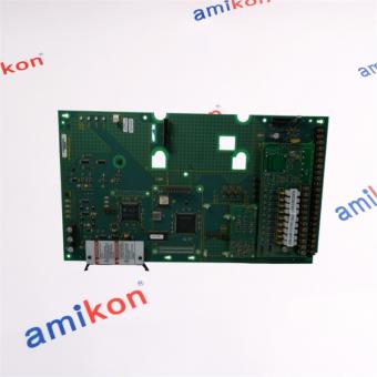


 IPv6 network supported