

| YOKOGAWA STARDOM I/O | PRODUCT SPECIFICATIONS SERIES CONTACT FAQ RECOMMENDED |
|
YOKOGAWA / STARDOM / ANALOG I/O
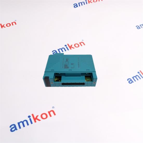
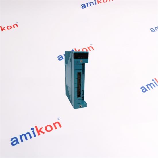
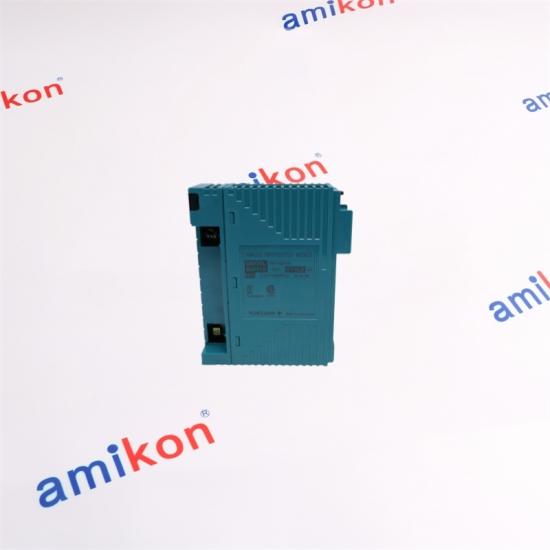
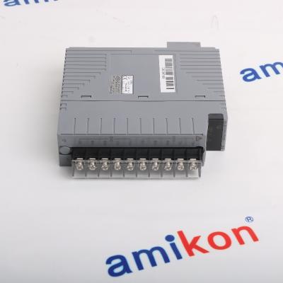
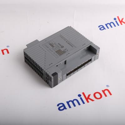
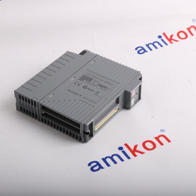
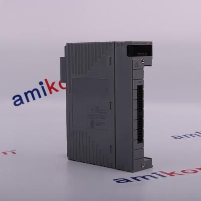
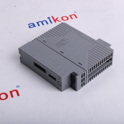
NFAI835-S50
4-Channel Input / 4-Channel Output Analog I/O Module
Isolated 4–20 mA analog signal interface for modular industrial control architectures
|
SIGNAL ARCHITECTURE
Analog I/O
Interface
|
|
Designed for Mixed Analog Loops
The NFAI835 family combines four analog current inputs and four analog current outputs in one module. Both input and output signals use the 4 to 20 mA range, making the module suitable for control architectures where measurement and analog command signals need to coexist in a compact I/O arrangement. The isolated-channel architecture separates the I/O signal paths from the system and provides isolation between channels. This architecture is useful when different field circuits must be handled without treating all analog channels as a single electrical domain. For engineering replacement or expansion work, attention should be given not only to the base NFAI835 model but also to the complete suffix configuration, terminal arrangement, temperature requirement and system compatibility.
|
ENGINEERING SNAPSHOT
|
| PARAMETER | INPUT | OUTPUT / MODULE |
| I/O Channels | 4 channels | 4 channels |
| Signal | 4–20 mA DC | 4–20 mA DC |
| Allowable Input Current | 25 mA | — |
| Input Resistance | 250 Ω, power ON | 500 kΩ or more, power OFF |
| Allowable Load Resistance | — | 0–750 Ω |
| Circuit-Open Detection | — | 0.65 mA or less |
| Accuracy | ±0.1% of full scale | ±0.3% of full scale |
| Data Refresh Cycle | 10 ms | 10 ms |
| Step Response | 100 ms | 100 ms |
| Withstand Voltage | 500 V AC for 1 minute between input/output and system, and between channels | |
| Transmitter Power Supply | 20.2–29.3 V DC | |
| Temperature Drift | Maximum ±0.01% / °C | |
| Maximum Current Consumption | 360 mA at 5 V DC; 450 mA at 24 V DC | |
| Weight | Approximately 0.3 kg | |
| External Connection | Pressure-clamp terminal / MIL connector cable depending on configuration | |
|
01 / Complete Part Configuration
NFAI835 appears with different suffix configurations. For replacement work, the complete ordering configuration should be matched rather than relying only on the NFAI835 base designation. |
02 / Terminal Arrangement
Confirm the required terminal and cable arrangement before ordering. S50 configurations are available with different connection-related suffix combinations. |
|
03 / Signal Requirements
The NFAI835 is designed for 4–20 mA current signals. Verify that the existing field loops and control logic use the same signal range and that the output-side load falls within the permitted range. |
04 / System Compatibility
Check the host FCN/FCN-RTU architecture, installed base module, connector arrangement and surrounding I/O configuration before introducing a replacement module. |
| MODEL FAMILY | INPUT | OUTPUT | ARCHITECTURE |
| NFAI835 | 4 × 4–20 mA | 4 × 4–20 mA | Isolated channels |
| NFAI841 | 8 × 4–20 mA | 8 × 4–20 mA | Non-isolated |
| NFAI135 | 8 × 4–20 mA | — | Isolated input channels |
| NFAI543 | — | 16 × 4–20 mA | Isolated output channels |
|
PURCHASE SUPPORT
Need NFAI835-S50?
Send the complete part number, required quantity, destination and required date. We can help check configuration details and arrange international delivery.
|
EMAIL SALES WHATSAPP SALES
Part Number · Quantity · Destination · Required Date · Machine/System
|
| 01 |
Can NFAI835-S50 replace an existing NFAI835 module without changing the field wiring?
The base NFAI835 function is four 4–20 mA inputs and four 4–20 mA outputs with isolated channels, but the complete suffix configuration determines connection-related details. Before replacement, compare the installed full part number, terminal arrangement, cable type and surrounding FCN configuration. A module that shares the NFAI835 base designation should not automatically be treated as electrically identical in every installation. |
| 02 |
Why does NFAI835-S50 use individual channel isolation instead of a common signal reference?
NFAI835 is specified with isolation between the input/output signal domain and the system as well as between channels. For a replacement application, this matters when field loops have different electrical conditions or when the installation requires separation between analog circuits. It is therefore important not to substitute a non-isolated analog I/O module simply because its signal range is also 4–20 mA. |
| 03 |
What should be checked if an NFAI835-S50 output loop has a high load resistance?
The specified allowable load resistance for the NFAI835 output is 0–750 Ω. If the field loop has a higher total resistance, the loop design should be reviewed before replacement. Cable resistance, receiving-device input resistance and other series elements should all be considered when determining the actual loop load. |
| 04 |
Is NFAI835-S50 suitable when both measurement and control signals are required in the same I/O area?
Yes. The NFAI835 architecture provides four analog input channels and four analog output channels, all using 4–20 mA signals. This makes it appropriate for installations where measurement loops and analog command loops need to be handled within the same module. The isolated architecture also keeps the individual signal paths electrically separated. |
| 05 |
Does the NFAI835-S50 configuration need to be matched when ordering a spare module?
Yes. Yokogawa provides multiple NFAI835 suffix configurations, including S50 combinations associated with different connection arrangements. For a spare-part order, the safest approach is to match the complete designation from the installed module and verify the required connector, terminal and system arrangement before shipment. |
|
01 / 7 DAYS
Please contact us within 7 days if you have any question after you receiving the items.
|
02 / CONDITION
The returned items has to be in its original condition, with a specific reason for the return.
|
03 / RESOLUTION
We will issue a return or replacement for your order after we received the returns.
|
04 / SHIPPING
The buyer is responsible for all the shipping cost incurred.
|
| 5453-754 | IC695ACC400 | IC695CPE305-BHAE | Tricon 4329 | 5441-693 |
| S2MDV843-0S1030 | IMDSI14 | EZ1080-07-00-050 | ST161 | INPRO3100I/SG/120 |
| F7133 | PW484-50 | IC200BEM003-CA | VI702 | IC695ACC402 |
| IC695CPE302-BBAB | PW481-51 | AAP135-S50 | IC693CPU350-CG | MTL5041 |
| IC695PSD140 | IC693CPU350 | IMFEC12 | IC693CPU374 | 133388-02 |
| IC695CPE305 | AAI143-S50 | 5501-367 | IC695ACC400-AA | KJ3241X1-BA2 |
| IC693CPU374-KZ | MVME167-02B | 9905-969 | F7130A | A2EN501-S00000 |
| ALR121-S51 | Tricon 4351 | MVME167-034B | MTL838C | 135489-01 |
| IC695RMX128 | IC695PSD140E | 80SD100XD.C0XX-21 | 2100P | DVC6200 |
| NFBU200-S15 | IC693CPU372 | IC695CPE330 | MVME167-033B | 1VCR017053G0006 |
| SIGA-MCT2 | AAI841-H50 | ANB10D-425-CU2N | MVME167-032A | SAI143-S33 |
| MMS6823 | Tricon 4119A | IC693BEM340-DE | 5MP050.0653-03 | F7131 |


Inventory Products


More than 40.000.000 products available and worldwide support


 Trust Guaranteed
 Customer Support





 IPv6 network supported