

|
YOKOGAWA / CENTUM VP / ESB NETWORK
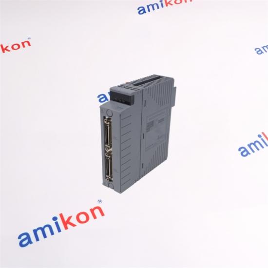
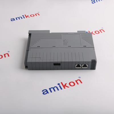
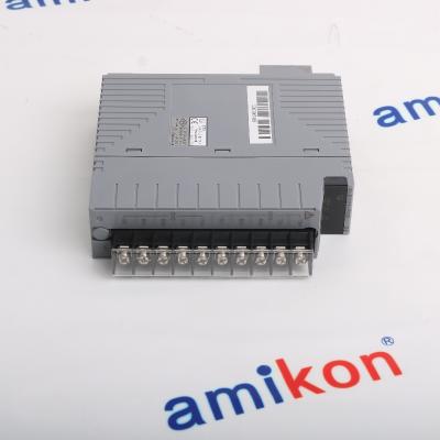
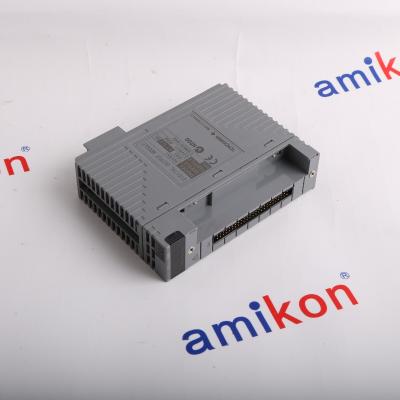
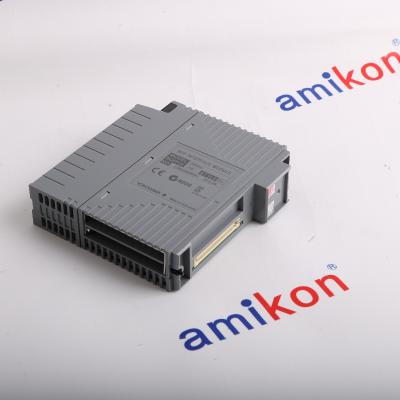
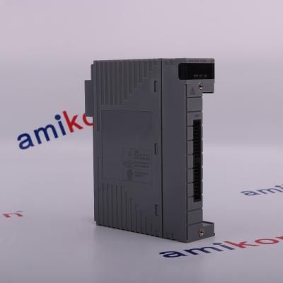
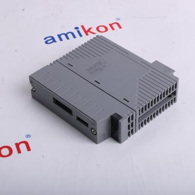
2-PORT ESB BUS COUPLER
EC402-51
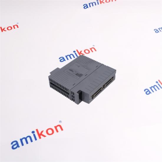
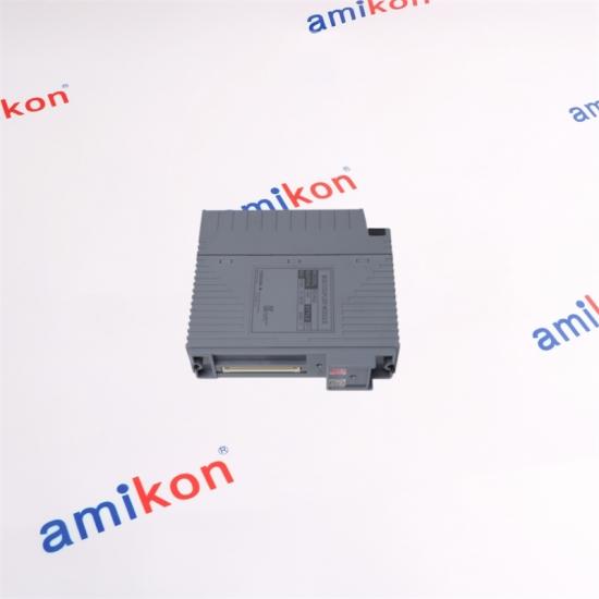
ESB Bus Coupler Module for N-IO/FIO — dual-port architecture for connecting a Field Control Unit with ESB bus Node Units.
A compact communication point between the control-unit layer and ESB bus node architecture.
|
CORE PARAMETERS
|
|
01 / ROLE
Bus Master Interface
EC402 provides the ESB bus master interface function used to connect a Field Control Unit with ESB bus Node Units.
|
02 / CONNECTION CONCEPT
Two Front ESB Bus Connector Ports
The EC402 architecture provides two ESB bus connector ports on the front of the module. The upper and lower sides can each accommodate up to 9 applicable node units under the standard connection condition. The published maximum transmission distance is 10 m on the upper side and 10 m on the lower side, giving a total maximum of 20 m.
|
||||
|
03 / DATA RATE
128
Mbps
I/O module data transmission
|
04 / REDUNDANCY
Single or Dual-Redundant ESB Bus Arrangement
One EC402 can be used for a non-redundant ESB bus arrangement. For a dual-redundant ESB bus configuration, two EC402 modules are installed in the Field Control Unit. The installation position for the ESB Bus Coupler Module is defined by the FCU configuration: the module occupies slot 7 in a non-redundant arrangement, while both slots 7 and 8 are used when the ESB bus is dual-redundant.
|
| Parameter | EC402-51 Value |
| Module function | ESB bus master interface function |
| Module type | ESB Bus Coupler Module, 2-Port |
| Supported system position | Field Control Unit for FIO |
| Transmission speed | 128 Mbps for I/O module data transmission |
| Upper-side connection | Maximum 9 applicable node units under the standard connection condition |
| Lower-side connection | Maximum 9 applicable node units under the standard connection condition |
| Upper-side transmission distance | Maximum 10 m |
| Lower-side transmission distance | Maximum 10 m |
| Total transmission distance | Maximum 20 m |
| Current consumption | 0.5 A |
| Approximate weight | 0.24 kg |
| Module dimensions | Approx. 32.8 × 129.5 × 130 mm |
| Base suffix | -5, standard type with no explosion protection |
| EC402-51 configuration | -5 standard type + suffix 1, ISA Standard G3 option |
|
SYSTEM FIT
Where EC402-51 Matters
The EC402 is positioned between the Field Control Unit and ESB bus Node Units. This makes the module particularly relevant when an existing CENTUM VP FIO architecture requires a two-port ESB bus connection or a dual-redundant ESB bus arrangement.
|
FIELD CONTROL UNIT
AFV30S / AFV30D / AFV40S / AFV40D
EC402 is installed in the FCU for the ESB bus connection.
↓
ESB BUS NODE SIDE
ANB10S / ANB10D / ANB11S / ANB11D
The ESB bus provides the communication path between the control-unit side and applicable node-unit side.
|
|
EC401
ESB Bus Coupler Module for FIO. It is the related coupler family member to consider when the required architecture does not call for the EC402 two-port arrangement.
|
EC402-50
EC402 standard configuration with the -5 suffix and basic option code 0. The EC402 platform provides two ESB bus connector ports.
|
EC402-51
Standard -5 configuration combined with option code 1 for the ISA Standard G3 option.
|
EC402-E Series
Explosion-protection configuration of the EC402 family. The exact suffix and environmental conditions must match the intended installation configuration.
|
|
CONFIGURATION NOTES
Installation Logic for EC402-51
|
SPECIAL CONNECTION CONDITION
Up to 12 + 12 Units
When A2FV50S or A2FV50D is used for the FCU and a star connection is configured with ANT4□1, the EC402 architecture can support a maximum of 12 units on the upper side and 12 units on the lower side. This condition is supported by CENTUM VP R6.06 or later.
|
|
ORDERING FOCUS
EC402-51
|
When replacing an installed EC402 unit, match the complete model and suffix configuration rather than selecting only the EC402 base designation. EC402-51 combines the standard -5 configuration with option code 1 for the ISA Standard G3 option. For an existing system, the FCU slot arrangement, ESB redundancy requirement, connected node architecture and applicable environmental configuration should all be checked before substitution.
|
|
SALES MANAGER
Miya Zheng
Email: sales@amikon.cn
Phone / WhatsApp: +86 180 2077 6792
|
REQUEST DETAILS
|
| 01 |
Can EC402-51 replace another EC402 when the installed system uses a dual-redundant ESB bus?
The EC402 architecture supports dual-redundant ESB bus operation by installing two EC402 modules in the FCU. A replacement should therefore match the installed EC402 suffix configuration and the system's redundancy arrangement. EC402-51 specifically includes the ISA Standard G3 option, so the existing unit's suffix and environmental requirements should be matched before substitution.
|
| 02 |
What should be checked before substituting an EC402-51 into an existing CENTUM VP FCU?
Check the FCU model, slot arrangement, ESB redundancy requirement, connected node structure, complete EC402 suffix configuration and the environmental requirements of the installation. For a non-redundant ESB bus, the EC402 occupies slot 7 and slot 8 is covered by a dummy module; for dual redundancy, EC402 modules occupy slots 7 and 8.
|
| 03 |
Does EC402-51 provide enough ESB capacity for a system with more than nine nodes on one side?
Under the standard connection condition, EC402 supports up to 9 applicable node units on each side. A special configuration can increase this to up to 12 units on each side when A2FV50S or A2FV50D is used for the FCU and a star connection is configured with ANT4□1, subject to the applicable CENTUM VP release condition. This should be verified against the actual system configuration before expansion.
|
| 04 |
Why does the EC402-51 suffix matter when ordering a replacement for an EC402 installation?
EC402 is available with different suffix combinations. The -5 suffix denotes the standard type without explosion protection, while the final option code 1 denotes the ISA Standard G3 option. EC402-51 therefore represents a specific configuration rather than merely the EC402 base model. Matching the complete suffix reduces the risk of selecting an unsuitable configuration for an existing installation.
|
| 05 |
Is EC402-51 suitable when an existing ESB layout needs a longer two-direction connection than EC401?
EC402 uses two ESB bus connector ports and provides up to 10 m on the upper side and up to 10 m on the lower side, for a published total maximum of 20 m. The EC402 is therefore the two-port member of the coupler family intended for the applicable two-direction ESB arrangement. Actual suitability still depends on the FCU, node arrangement and connection topology.
|
|
DELIVERY
3–5 Days
|
WARRANTY
12 Months
|
PACKAGING
Brand New
|
DELIVERY WAY
DHL / UPS / FedEx / EMS / TNT
|
PAYMENT
T/T
|
|
Returns & Replacement
7-day post-receipt support window
|
Please contact us within 7 days if you have any question after you receiving the items. The returned items has to be in its original condition, specific reason for the return, we will issue a return or replacement for your order after we received the returns. The buyer is responsible for all the shipping cost incurred.
|
| IC695CPE330 | MTL838C | 2612602 | AAI143-S50 | IC200BEM003-CA |
| DVC6200 | 6SL3210-1KE32-4UF1 | ST161 | 133388-02 | SIP10 |
| X20AO2622 | IC693CPU350-CG | NFBU200-S15 | A2EN501-S00000 | 2100P |
| IC695ACC400-AA | DR4900 | MTL5041 | 6SE7038-6EK84-1JC2 | S2MDV843-0S1030 |
| X20DO4529 | IC693BEM340-DE | 1900C | SAI143-S33 | TL2360 |
| 6SL3210-1KE27-0AF1 | CDC40105 | A5E00714560 | IC695RMX128 | CP360 |
| EZ1080-07-00-050 | IMFEC12 | PHC805 | 1VCR017053G0006 | IC693CPU374 |
| DR5000 | IC695CPE305-BHAE | MMS6823 | LQV157 | 3RK1903-3BA02 |
| IC693CPU372 | PHC281 | A5E00714561 | IC695ACC402 | MMK-6L |
| ISENH3181 | DR2800 | IC693CPU374-KZ | SENSION156 | 8I66T400037.0X-000 |
| IC695CPE305 | IC693CPU350 | A5E00714561 | SAI143-S33 | K5061WHI |
| IC200ALG328D | LICO500 | IC695CPE305 | CP360 | SX5457M RJ45 |


Inventory Products


More than 40.000.000 products available and worldwide support


 Trust Guaranteed
 Customer Support








 IPv6 network supported