Pulse Input Architecture for High-Integrity Field Signal Acquisition
08
Isolated input channels
0–10
kHz input frequency
40 μs
Minimum input pulse width
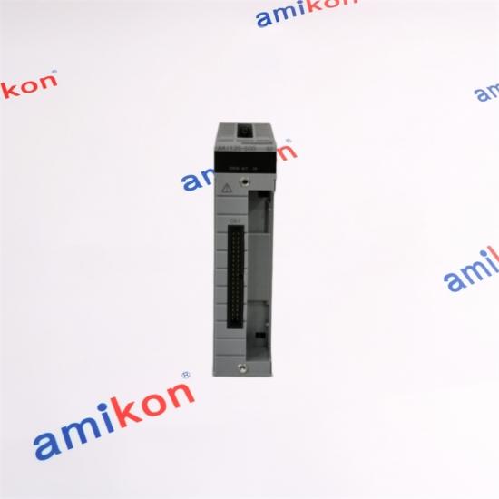
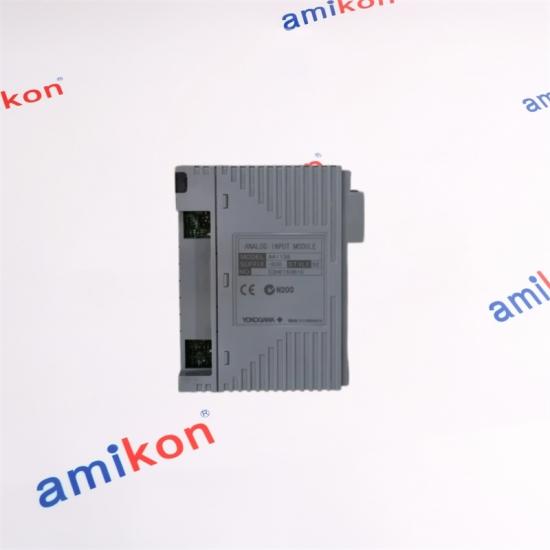
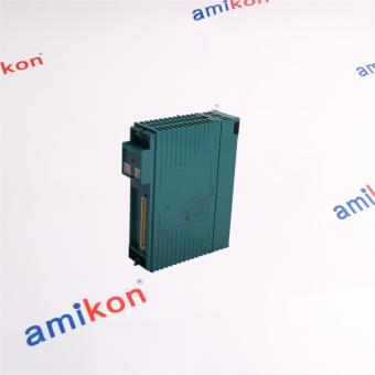
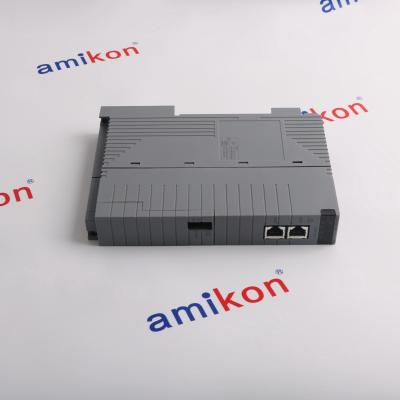
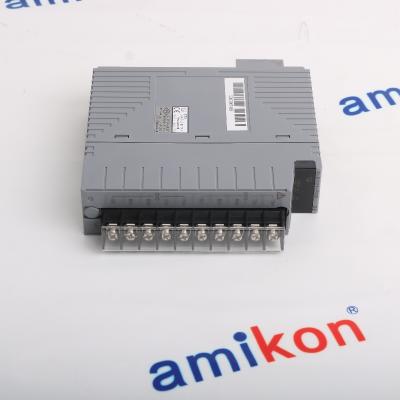
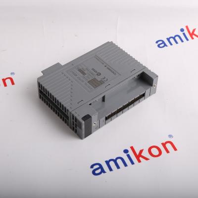
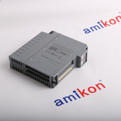
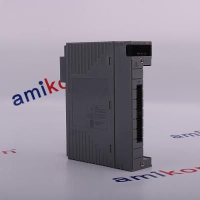
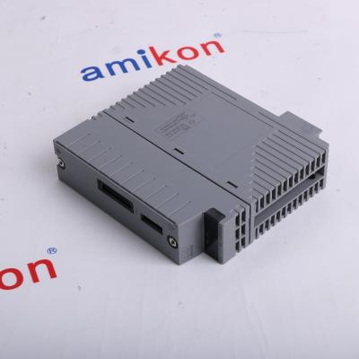
The ALP135-S50 page is structured around the Yokogawa AAP135 pulse-input architecture: an eight-channel isolated module designed to receive contact ON/OFF, voltage-pulse and current-pulse signals, including three-wire power-supply-type voltage pulses.
PULSE INPUT
AAP135
8-CHANNEL / ISOLATED
0–10 kHz
01
01 / PRODUCT CORE
Pulse Signal Processing
Eight-channel acquisition
The AAP135 architecture provides eight isolated pulse-input channels, allowing multiple field pulse sources to be handled within one compact I/O module.
Signal flexibility
Supported signal arrangements include contact ON/OFF, voltage pulse, current pulse and three-wire power-supply-type voltage pulse inputs.
High-speed pulse range
The specified input-frequency range extends from 0 to 10 kHz, suitable for pulse-counting applications requiring substantially faster signal acquisition than low-speed contact monitoring.
Independent channel isolation
Isolation is provided between the input and system and between individual channels, helping separate field-side signal circuits from one another.
SIGNAL FLOW
FIELD PULSE
↓
INPUT CONDITIONING
↓
ISOLATED CHANNEL
↓
SYSTEM DATA
02 / SIGNAL HANDLING
Built Around Pulse Integrity
The module accepts pulse-type field signals and converts them into pulse-count data for the control system. The design supports both contact-based and electronic pulse sources.
Contact ON/OFF Relay or transistor contact input
Voltage Pulse Electronic pulse signal acquisition
Current Pulse Current-pulse signal input
Three-Wire Pulse Power-supply-type voltage pulse
02
TECHNICAL PROFILE
ALP135-S50 / AAP135 Architecture
Parameter
Specification
Module Type
Pulse Input Module
Input Channels
8 isolated channels
Input Frequency
0 to 10 kHz
Minimum Input Pulse Width
40 μs
2-Wire Input
Contact ON/OFF, voltage pulse, current pulse
3-Wire Input
Power-supply-type voltage pulse
Input/System Withstand
500 V AC for 1 minute
Channel-to-Channel Withstand
500 V AC for 1 minute
Data Update Period
2 ms
Transmitter Power Supply
Selectable 12 V DC / 24 V DC
Contact Input Open Level
100 kΩ or larger
Contact Input Close Level
200 Ω or less
Voltage Pulse High Level
3 to 24 V DC
Voltage Pulse Low Level
−1 to 8 V DC
Signal Swing
3 V or higher
Signal Source Resistance
1 kΩ or less
03 / CONFIGURATION
Connection Architecture
The AAP135 family supports several field connection arrangements through dedicated interface options.
Cable Interface
KS cable interface adapter options are available for the AAP135 configuration, including ATI3A and ATK4A arrangements.
Pressure Clamp
Pressure-clamp terminal arrangements are available for pulse connections, including standard and surge-absorber variants.
Dual Pressure Clamp
Dual pressure-clamp arrangements provide another termination option for pulse-input installation requirements.
MIL Cable Interface
Connector-cover options are available for MIL cable configurations.
16-channel pulse count, 0–6 kHz, non-isolated architecture. Its channel count and isolation arrangement differ from AAP135.
AAP849
Pulse Input / Analog Output
8 pulse inputs and 8 analog outputs with a non-isolated architecture. It serves a different I/O combination from the dedicated AAP135 pulse-input role.
Selection logic: AAP135 is the relevant architecture when the application requires isolated pulse counting with an input-frequency range up to 10 kHz. AAP149 and AAP849 differ in channel architecture, isolation and I/O function, so direct substitution should be based on the actual system design.
04 / DIRECT INQUIRY
Ready for Your Automation Requirement
Send the exact part number, required quantity, destination and required date. For system compatibility, also include the machine or control-system application.
Please contact us within 7 days if you have any question after you receiving the items.
The returned items has to be in its original condition, with a specific reason for the return. We will issue a return or replacement for your order after we receive the returns.
The buyer is responsible for all the shipping cost incurred.
05 / PURCHASING QUESTIONS
ALP135-S50 FAQ
Can ALP135-S50 handle pulse sources that are electrically separated from other channels?
The AAP135 architecture is designed with eight isolated channels, with isolation specified both between the input and system and between channels. This makes the architecture appropriate where channel separation is part of the signal design.
Is ALP135-S50 suitable when the pulse frequency approaches the upper range of the module?
The AAP135 specification defines an input-frequency range of 0 to 10 kHz. Applications should therefore be checked against the actual pulse frequency and minimum pulse width before ordering.
What should be checked before replacing ALP135-S50 with another pulse-input module?
Channel count, isolation architecture, pulse-frequency range, signal type and terminal/interface arrangement should all be checked. AAP149, for example, has 16 non-isolated channels and a 0–6 kHz range, so it is not a direct specification match for the AAP135 architecture.
Does ALP135-S50 support both contact signals and electronic pulse signals?
The AAP135 input architecture supports 2-wire contact ON/OFF, voltage pulse and current pulse signals, as well as 3-wire power-supply-type voltage pulse signals. The selected field wiring must match the applicable input arrangement.
Which ALP135-S50 connection option should be confirmed for an existing installation?
The connection arrangement should be matched to the existing field termination. The AAP135 family supports KS cable interface adapters, pressure-clamp terminal arrangements, dual pressure-clamp arrangements and MIL cable interface options. Confirming the installed interface before ordering helps avoid a terminal mismatch.
AMIKON GLOBAL AUTOMATION PARTS
CONNECTED BY PARTS
EXCLUSIVE MULTILINGUAL SUPPORT
01 / CUSTOMER CONNECTION
Exclusive Multilingual Support Team
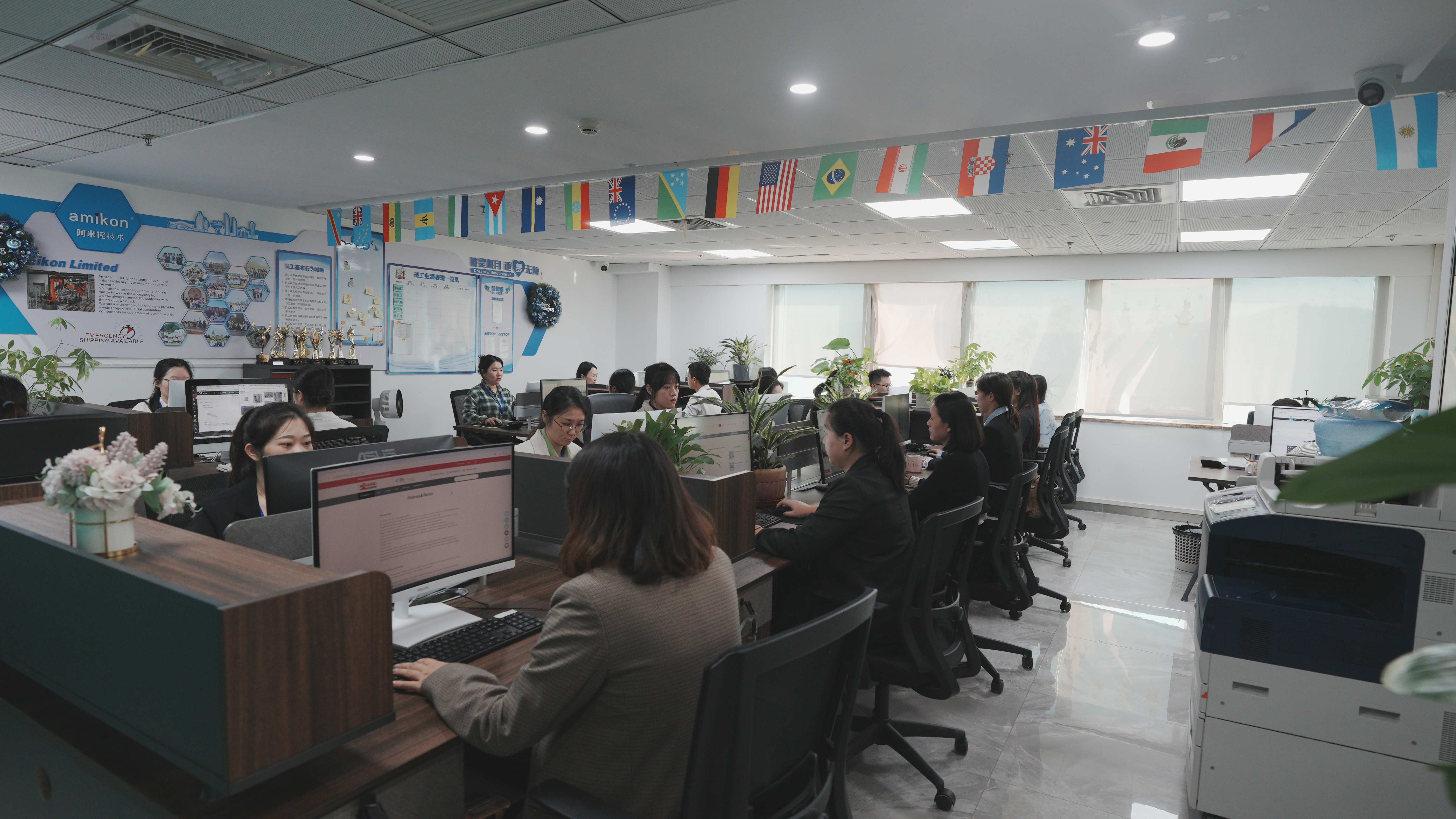
Clear communication across international purchasing, technical confirmation and order coordination.
GLOBAL SUPPORTFAST RESPONSE
CUSTOMIZED ORDER TRACKING
02 / ORDER CONTROL
Customized Customer Relation Management
& Order Tracking System
Structured order coordination helps keep part numbers, quantities, destinations and delivery requirements aligned throughout the purchasing process.
ORDER CONTROLTRACEABLE PROCESS
CONNECT THROUGH PARTS
03 / GLOBAL SUPPLY
No Additional Charges, Handling Charges
or Hidden Charges Are Incurred
We continue to innovate and strive to improve the world's automation parts supply level. Wherever the customer is located or however difficult a part may be to find, we aim to connect customers through automation parts.
Worldwide Parts CoverageIndustrial AutomationGlobal Delivery




 Trust Guaranteed
 Customer Support




 IPv6 network supported