

|
BRAND |
WOODWARD |
|
Model |
9907-028 |
|
|
|

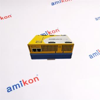
Model 9907-028
WOODWARD ⇒ USA ⇒ SPM-A Synchronizer

Applications
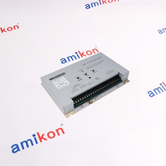
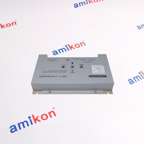
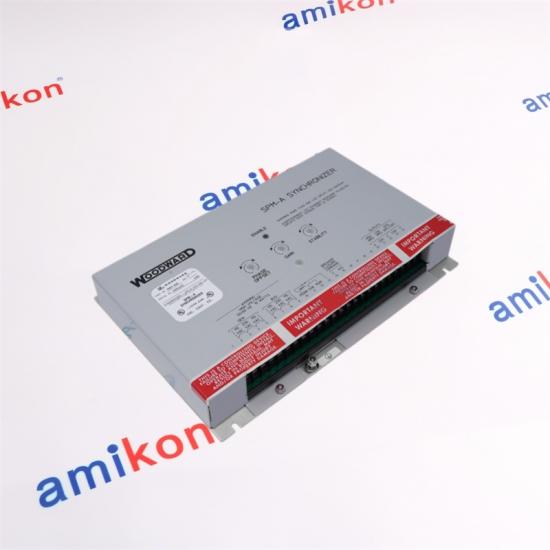
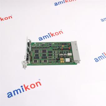
Woodward’s SPM-A Speed and Phase Matching Synchronizer provides automatic frequency and phase matching when used with 2301, 2301A, and Electrically Powered Governor (EPG) electric load sharing control systems.
Description
The SPM-A Synchronizer automatically generates a signal to bias the speed of the prime mover of an off-line generator so that its frequency and phase match those of the bus. Tight control action is obtained by feeding the synchronizer’s speed bias signals directly into the electronic control’s speed loop error amplifier rather than through a motor-operated speed-setting potentiometer. The synchronizer automatically issues a signal to close the circuit breaker connecting the off-line unit to the bus when phase and frequency are matched within limits.
Four operating modes (Run, Check, Permissive, and Off) facilitate system testing and installation checkout without electrically disconnecting the synchronizer from the control system. These four modes are selected by an external switch (customer supplied) connected to the SPM-A Synchronizer.
The RUN mode allows synchronization and automatic breaker closure.
The CHECK mode allows testing correct synchronizing operation, but without circuit breaker closure.
The PERMISSIVE mode allows checking for acceptable synchronization, but does not trim speed or adjust voltage. If synchronization is correct, the breaker is allowed to close.
In the OFF mode, the synchronizer is out of operation.
The synchronizers are used in generator installations. Dynamics are adjustable. Only one model is required for fast or slow dynamics. The synchronizer is compatible with small or large diesels, gasoline or gas engines, and steam or gas turbines. Fast dynamics are designed to match the fast dynamics of small- to medium-size diesel engines. Slow dynamics are designed to match the slower dynamics of large diesel engines and turbomachinery and gas or gasoline engines.
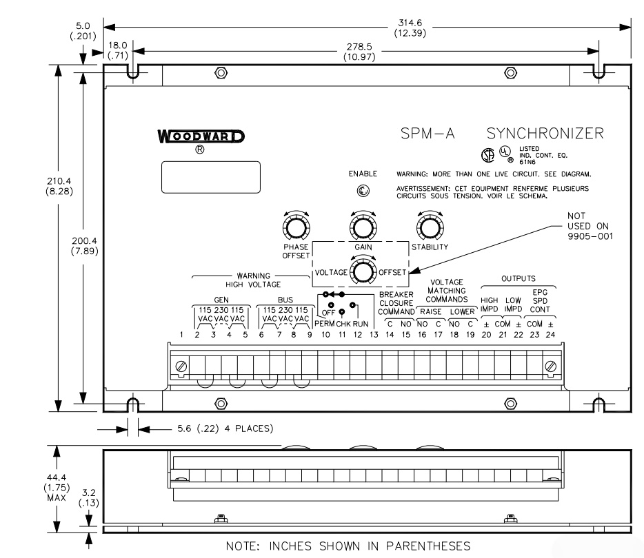
There are four distinct functions in the SPM–A Synchronizer: the speed bias circuit, the enable circuit, the breaker closure circuit, and the voltage comparator circuit.
l Speed Bias Circuit
By using the phase lock technique to compare bus and generator voltages, the speed bias circuit output causes the off-line generator set, through the bias circuit to the electronic control, to alter speed to match the bus phase angle. A lockout circuit disconnects the speed bias output when the close breaker command ceases. The synchronizer output then remains disconnected until it is automatically reset. This reset will take place if the speed of the oncoming unit drifts outside the permissive synchronizing window.
l Enable Circuit
The enable circuit provides a secondary relative phase angle check and a coarse bus and generator voltage comparison. When conditions are acceptable, the enable circuit permits the breaker close circuit to issue a close breaker command. The enable circuit increases system reliability by preventing single-point failures from causing the close breaker command to be erroneously issued.
l Breaker Close Circuit
The breaker close output, unless inhibited by the enable circuit, issues the command to close the main breaker if conditions are acceptable. If the relative phase angle between the bus and the generator voltages is zero and stays zero while the main breaker is closing, perfect synchronization and paralleling result. It is not necessary that the phase angle always be zero, just that the phase angle be less than the greatest allowable value, which is +10 degrees (within the “window”) and has been within the window for the window dwell time. The synchronizer's phase match window dwell time may be chosen (by an internal selection switch for 1/8, 1/4, 1/2, or 1 second) to ensure that the phase angle is less than the greatest allowable phase difference when the breaker contacts engage. The close breaker command consists of the breaker close relay changing state for about one second.
l Voltage Comparator Circuit
In the voltage matching model, the voltage comparator circuit of the synchronizer compares bus and off-line generator voltages. When voltages are equal, there is no comparator circuit output. If a difference of input voltage exists, an increase or decrease relay signal is sent to the generator's voltage regulator. Where a difference in voltage exists, the breaker closure circuit and the speed/phase output are inhibited.

FAQ
Q1: How does the WOODWARD 9907-028 optimize governor control accuracy and dynamic response in demanding prime mover applications?
The WOODWARD 9907-028 is engineered to deliver precise speed regulation and rapid transient response by utilizing advanced electronic governor control algorithms. It helps maintain stable engine or turbine operation during load variations while improving overall system reliability and operational efficiency.

Q2: Why is the WOODWARD 9907-028 considered a robust solution for integrating with industrial engine and turbine control architectures?
The WOODWARD 9907-028 is designed for seamless integration into industrial control systems, supporting dependable communication with compatible actuators, sensors, and governor components. Its rugged construction and industrial-grade design make it suitable for continuous operation in harsh environments.

Q3: What operational parameters can the WOODWARD 9907-028 precisely regulate to enhance power generation stability?
The WOODWARD 9907-028 is capable of accurately regulating critical engine parameters such as speed, load sharing, and governor response characteristics. This precise control contributes to improved frequency stability, optimized load acceptance, and enhanced overall generator performance.

Q4: Which engineering considerations should be evaluated before commissioning the WOODWARD 9907-028 in a governor control system?
Before installing the WOODWARD 9907-028, engineers should verify power supply compatibility, wiring configuration, actuator matching, calibration settings, environmental operating conditions, and compliance with the recommended installation procedures to ensure optimal performance and long-term reliability.

Q5: How does the WOODWARD 9907-028 contribute to minimizing maintenance requirements and maximizing lifecycle performance?
The WOODWARD 9907-028 incorporates a durable electronic design with stable control performance and dependable operating characteristics. Its reliable architecture reduces unexpected downtime, simplifies preventive maintenance, and supports extended service life in mission-critical industrial power generation and engine control applications.
If you NEED other PLC DCS products, please Contact us NOW !
Miya zheng (sales manager)
Email : sales@amikon.cn
WeChat : 86-18020776792
MobilePhone/WhatsApp : 86-18020776792
Recommended
|
5461-648 |
5462-758B |
5438-667 |
|
5461-644 |
5461-650 |
5464-643 |
|
5462-718 |
5462-744 |
5464-648 |
|
5462-757 |
9907-164 |
5464-653 |
|
5462-948 |
8271-467 |
5464-850 |
|
5462-408 |
9905-068 2301A |
5466-026 |
|
5500-577 |
9905-792 |
5466-352 |
|
5462-916 |
CMW112 |
9907-029 |

Amikon - We serve all walks of life in worldwide, help to provide and support their business processes, and adapt to the specific needs of each industry. PLC : Allen Bradley Rockwell, GE FANUC, Schneider Modicon Quantum DCS : ABB, Siemens MOORE, Foxboro, Westinghouse, YOKOGAWA ESD : Triconex, HIMA, Bently Nevada, ICS Triplex Excitation Cards : ABB, GE Marke Sales manager : Jessica | Email : sales3@amikon.cn Mobile : 86-18030235311 | Skype : jessica01235483

Amikon - We serve all walks of life in worldwide, help to provide and support their business processes, and adapt to the specific needs of each industry. PLC : Allen Bradley Rockwell, GE FANUC, Schneider Modicon Quantum DCS : ABB, Siemens MOORE, Foxboro, Westinghouse, YOKOGAWA ESD : Triconex, HIMA, Bently Nevada, ICS Triplex Excitation Cards : ABB, GE Marke Sales manager : Jessica | Email : sales3@amikon.cn Mobile : 86-18030235311 | Skype : jessica01235483

Amikon - We serve all walks of life in worldwide, help to provide and support their business processes, and adapt to the specific needs of each industry. PLC : Allen Bradley Rockwell, GE FANUC, Schneider Modicon Quantum DCS : ABB, Siemens MOORE, Foxboro, Westinghouse, YOKOGAWA ESD : Triconex, HIMA, Bently Nevada, ICS Triplex Excitation Cards : ABB, GE Marke Sales manager : Jessica | Email : sales3@amikon.cn Mobile : 86-18030235311 | Skype : jessica01235483

Amikon - We serve all walks of life in worldwide, help to provide and support their business processes, and adapt to the specific needs of each industry. PLC : Allen Bradley Rockwell, GE FANUC, Schneider Modicon Quantum DCS : ABB, Siemens MOORE, Foxboro, Westinghouse, YOKOGAWA ESD : Triconex, HIMA, Bently Nevada, ICS Triplex Excitation Cards : ABB, GE Marke Sales manager : Jessica | Email : sales3@amikon.cn Mobile : 86-18030235311 | Skype : jessica01235483

Amikon - We serve all walks of life in worldwide, help to provide and support their business processes, and adapt to the specific needs of each industry. PLC : Allen Bradley Rockwell, GE FANUC, Schneider Modicon Quantum DCS : ABB, Siemens MOORE, Foxboro, Westinghouse, YOKOGAWA ESD : Triconex, HIMA, Bently Nevada, ICS Triplex Excitation Cards : ABB, GE Marke Sales manager : Jessica | Email : sales3@amikon.cn Mobile : 86-18030235311 | Skype : jessica01235483

Amikon - We serve all walks of life in worldwide, help to provide and support their business processes, and adapt to the specific needs of each industry. PLC : Allen Bradley Rockwell, GE FANUC, Schneider Modicon Quantum DCS : ABB, Siemens MOORE, Foxboro, Westinghouse, YOKOGAWA ESD : Triconex, HIMA, Bently Nevada, ICS Triplex Excitation Cards : ABB, GE Marke Sales manager : Jessica | Email : sales3@amikon.cn Mobile : 86-18030235311 | Skype : jessica01235483

Amikon - We serve all walks of life in worldwide, help to provide and support their business processes, and adapt to the specific needs of each industry. PLC : Allen Bradley Rockwell, GE FANUC, Schneider Modicon Quantum DCS : ABB, Siemens MOORE, Foxboro, Westinghouse, YOKOGAWA ESD : Triconex, HIMA, Bently Nevada, ICS Triplex Excitation Cards : ABB, GE Marke Sales manager : Jessica | Email : sales3@amikon.cn Mobile : 86-18030235311 | Skype : jessica01235483

Amikon - We serve all walks of life in worldwide, help to provide and support their business processes, and adapt to the specific needs of each industry. PLC : Allen Bradley Rockwell, GE FANUC, Schneider Modicon Quantum DCS : ABB, Siemens MOORE, Foxboro, Westinghouse, YOKOGAWA ESD : Triconex, HIMA, Bently Nevada, ICS Triplex Excitation Cards : ABB, GE Marke Sales manager : Jessica | Email : sales3@amikon.cn Mobile : 86-18030235311 | Skype : jessica01235483


Inventory Products


More than 40.000.000 products available and worldwide support


 Trust Guaranteed
 Customer Support


 IPv6 network supported