

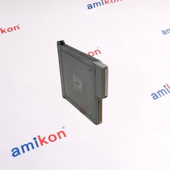
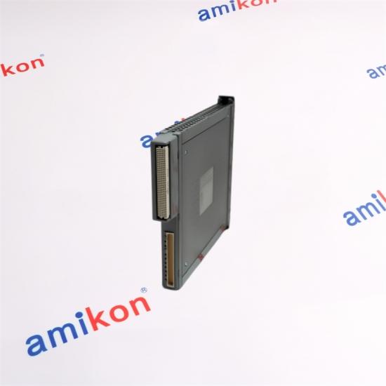
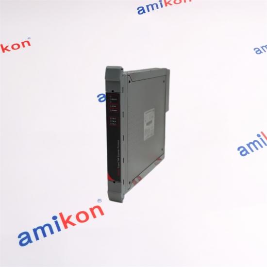
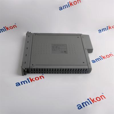
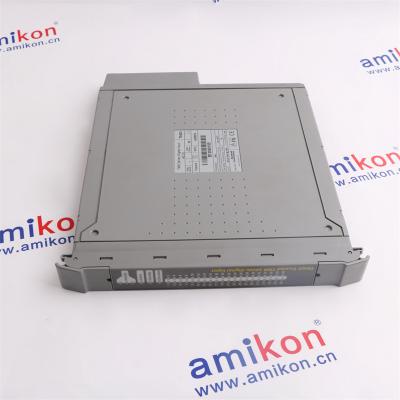
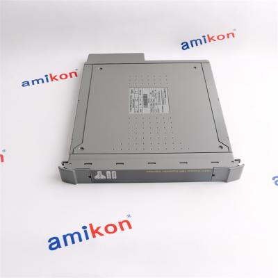
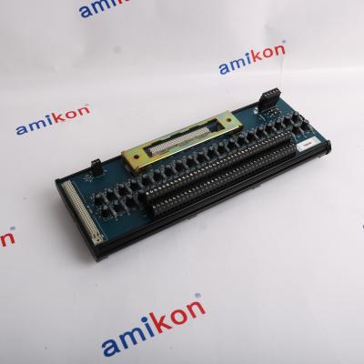
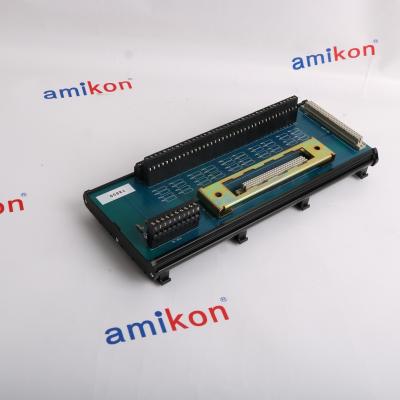
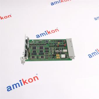
The ICS Triplex T8312-7C belongs to the Trusted TMR Expander Interface Adapter family. Its function is to provide the interconnection between Trusted Expander Interface Modules in the Controller Chassis and multiple Expander Chassis. The seven-way version is intended for architectures requiring connections to up to seven Expander Chassis.
The unit uses a 96-way C-type chassis connector together with seven 12-pin ODU connectors. It is enclosed in a metal housing and clips onto the rear connectors of the Controller Chassis. A release button allows the adapter to be disconnected when required during qualified maintenance work.
|
ARCHITECTURE
Seven-Way Expansion PathT8312-7C provides seven numbered expander connections. In the Trusted architecture, the first Expander Chassis is associated with address 2 and subsequent chassis use addresses through 8. The controller chassis uses virtual address 1, providing a logical sequence for the first group of expansion chassis. When a system requires more chassis than one interface can accommodate, an additional Expander Interface can be used. The additional chassis retain their local switch settings while their virtual addresses are assigned through the system configuration. |
EXPANDER CONNECTION MAP
|
||||||||||||||||||
|
◈
Seven Expander ConnectionsThe T8312-7 version provides interconnection for up to seven Expander Chassis, making it suitable where the Trusted architecture requires a larger expansion group. |
◇
250 Mbps Expander BusThe Expander Bus operates at 250 Mbps, providing the specified communication rate between the Trusted controller-side interface and connected expansion architecture. |
|
|
△
EMC-Shielded ConstructionThe adapter is fully shielded for electromagnetic compatibility and uses a metal enclosure around the PCB and connector assembly. |
□
Locking Connection DesignLocking connectors are used to improve connection security, while the rear clip-on arrangement provides a defined mechanical interface with the Controller Chassis. |
| Product Family | Trusted TMR Expander Interface Adapter Unit |
| Use With | T8100 / T8311 |
| Expander Bus Data Rate | 250 Mbps (0.25 Gbps) |
| Expander Connections | Seven 12-pin ODU connectors |
| Controller-Side Connector | Double 96-way DIN41612 C-type connector |
| Required Communications Cable | 250 MHz Communications Cable TC-301-01 |
| Enclosure | Metal enclosure with rear clip-on mounting arrangement |
| Operating Temperature | 0 °C to +60 °C (+32 °F to +140 °F) |
| Non-Operating Temperature | -25 °C to +70 °C (-13 °F to +158 °F) |
| Relative Humidity | 10%–95%, non-condensing |
| Dimensions | 130 mm × 60 mm × 115 mm (5.1 × 2.4 × 4.5 in) |
| Weight | 650 g (1.43 lb) |
|
04 / FAMILY POSITION
Trusted T8312 SeriesThe T8312 family provides the interface between Trusted controller-side Expander Interface Modules and Expander Chassis. |
For replacement planning, the critical selection point is the required number of connected Expander Chassis. The seven-way architecture is the appropriate family configuration when the existing system is built around the seven-expander arrangement. The exact chassis, connector, cable and configuration requirements should be checked before ordering. |
System ExpansionT8312-7C is used where the Trusted Controller Chassis must communicate with a group of Expander Chassis. Its seven-way arrangement provides the physical interface for the first group of seven expansion connections. The adapter therefore becomes particularly important when additional I/O architecture is distributed across multiple Trusted Expander Chassis rather than concentrated in the controller chassis. |
Replacement & Fault InvestigationIf communication with one or more Expander Chassis is interrupted, the adapter, its connectors and the associated communication cabling become part of the physical connection path that should be checked. Because T8312-7C uses multiple ODU connections and a double 96-way chassis connector, replacement planning should verify the connector arrangement, seven-way configuration and associated TC-301-01 communication cable before a unit is exchanged. |
| Confirm 7-way architecture |
Confirm T8100 / T8311 interface |
Confirm TC-301-01 cable |
Confirm Connector arrangement |
Q1. Is T8312-7C the correct choice when seven Trusted Expander Chassis must be connected?Yes. The T8312 family has a four-way and a seven-way configuration. T8312-7C corresponds to the seven-way arrangement, with seven 12-pin ODU connections for Expander Chassis. For a replacement, the existing system should be checked against the seven-expander architecture rather than selecting the part only by physical appearance. |
Q2. What should be checked before replacing T8312-7C in an operating Trusted installation?Check the Controller Chassis interface, the seven-way arrangement, the ODU connections and the associated TC-301-01 250 MHz communications cable. The Trusted technical material also specifies that the PCB contains static-sensitive components and that connector pins should not be touched. Maintenance work should be performed by qualified personnel. |
Q3. Can T8312-7C be selected simply because the older unit is marked T8312-7?The seven-way architecture is the key family characteristic, but a replacement should still be verified against the installed chassis, connector arrangement and environmental requirements. The “C” version should be ordered as the exact part number when the installed system or purchasing specification calls for T8312-7C. |
Q4. Why is the T8312-7C connector and cable combination important during replacement?The adapter is not a generic communication converter. Its controller-side interface is a double 96-way DIN41612 C-type connector, while the expander side uses seven 12-pin ODU connectors. The specified communication cable is the TC-301-01 250 MHz Communications Cable. Matching these interfaces is therefore an important part of replacement planning. |
Q5. What environmental specifications should be considered when purchasing T8312-7C?The specified operating temperature is 0 °C to +60 °C, with a non-operating range of -25 °C to +70 °C. Relative humidity for operating, storage and transport is specified as 10%–95%, non-condensing. The physical installation should also account for the 130 mm × 60 mm × 115 mm dimensions and approximately 650 g weight. |
If you have any question after receiving the items, please contact us within 7 days.
Returned items should remain in their original condition and include a specific reason for the return. After the returned items are received, we will arrange the applicable return or replacement for the order.
Shipping costs incurred for the return are the buyer's responsibility.
| LDO10105 | 6SE7033-2EG84-1JF1 | 3UM161.6 | 6AV6645-0CB01-0AX0 | AB7007-C | 6SL3320-1TG33-3AC3 |
| AM351 | 5AC901.IUPS-01 | DR3800 | 7DM465.7 | LICO500 | 6SN1145-1BA01-0BA1 |
| X20DI2372 | X67DM1321.L08 | PHC10101 | PHC281 | V600-D8KR04 | X20CP1486 |
| 5LS071.9 | X67BC8331 | 6SL3330-6TE41-1AA3 | ISENH3181 | HQ30D | LICO690 |
| 6FC5203-0AF02-0AA1 | 6SL3210-5HE17-0UF0 | DR1900 | X20CP1585 | 6SN1123-1AA00-0CA2 | 6SL3210-5HE15-0UF0 |
| LQV157 | DR5000 | 6SE7027-2TD84-1HF5 | 6SE7027-2TD61-Z | DR890 | 6SL3320-1TE33-1AA3 |
| 6SL3330-7TE32-1AA0 | 7AT664.70 | 6SL3210-5HE10-8UF0 | TL2360 | DR4900 | PHC805 |
| 3IF613.9 | X20MM2436 | 2612602 | 6SL3210-5HB10-4UF0 | 6SL3210-5HE11-0UF0 | DR900 |
| 0AK300.1 | X20AI4632-1 | 8B0C0320HW00.002-1 | DR6000 | 6SL3210-5HE13-5UF0 | 1KF2105-6AF10-0MA0 |
| PHC10103 | X20CP1584 | ASD18B-K | 6SN1123-1AA00-0DA2 | SIP10 | 6SL3210-5HB10-2UF0 |
Control Systems (DCS, PLC/SPS, CNC) - Panel Controllers - HMI and Display Panels - Input Output I/O - Industrial PC’s - Drives ( Frequency Inverter and Servo) - Motors Drives - Power Supplies The amikon advantage: more parts to more places, worldwide
Control Systems (DCS, PLC/SPS, CNC) - Panel Controllers - HMI and Display Panels - Input Output I/O - Industrial PC’s - Drives ( Frequency Inverter and Servo) - Motors Drives - Power Supplies The amikon advantage: more parts to more places, worldwide
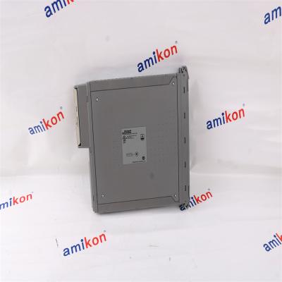
Product model T8461C Product Discription TMR 24/48 Vdc Digital Output Brand ICS TRIPLEX Weight 950g(2.1 Ib) Condition 100% New Production year 2024 country of origin USA
Control Systems (DCS, PLC/SPS, CNC) - Panel Controllers - HMI and Display Panels - Input Output I/O - Industrial PC’s - Drives ( Frequency Inverter and Servo) - Motors Drives - Power Supplies The amikon advantage: more parts to more places, worldwide
Control Systems (DCS, PLC/SPS, CNC) - Panel Controllers - HMI and Display Panels - Input Output I/O - Industrial PC’s - Drives ( Frequency Inverter and Servo) - Motors Drives - Power Supplies The amikon advantage: more parts to more places, worldwide

Control Systems (DCS, PLC/SPS, CNC) - Panel Controllers - HMI and Display Panels - Input Output I/O - Industrial PC’s - Drives ( Frequency Inverter and Servo) - Motors Drives - Power Supplies The amikon advantage: more parts to more places, worldwide
Control Systems (DCS, PLC/SPS, CNC) - Panel Controllers - HMI and Display Panels - Input Output I/O - Industrial PC’s - Drives ( Frequency Inverter and Servo) - Motors Drives - Power Supplies The amikon advantage: more parts to more places, worldwide
Control Systems (DCS, PLC/SPS, CNC) - Panel Controllers - HMI and Display Panels - Input Output I/O - Industrial PC’s - Drives ( Frequency Inverter and Servo) - Motors Drives - Power Supplies The amikon advantage: more parts to more places, worldwide


Inventory Products


More than 40.000.000 products available and worldwide support


 Trust Guaranteed
 Customer Support





 IPv6 network supported