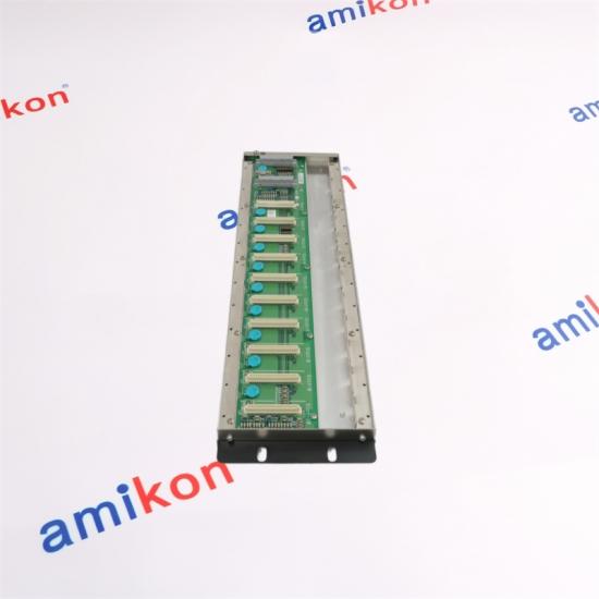
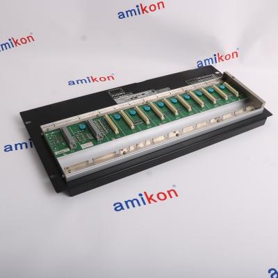
A modular rack-mounted foundation for Yokogawa FCN control configurations, providing the physical platform for CPU, power supply and I/O modules.
19-INCH RACKLONG BASE MODULE
MODEL SERIES
NFBU
200 · S05
YOKOGAWA
8
Max. I/O Modules*
2
Power Supply Slots
19"
Rack Mounting
1.9
Weight · kg
*The maximum of 8 I/O modules applies to a standard NFBU200 control-unit configuration. The available module positions depend on the installed CPU and expansion configuration.
01
A Structural Base for Modular Control
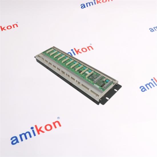
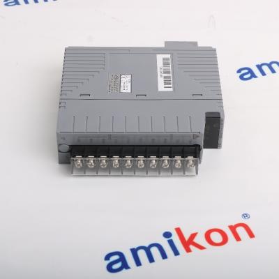
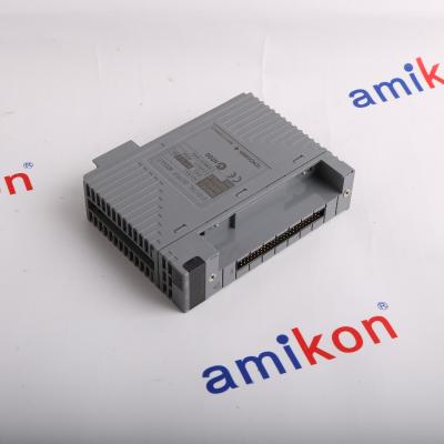
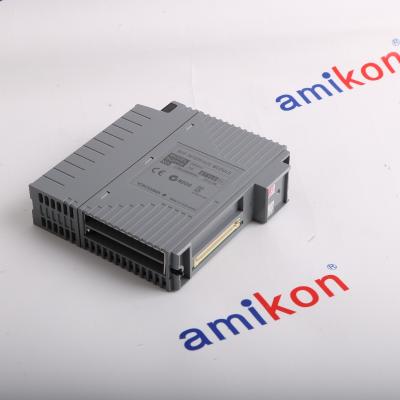
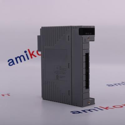
The Yokogawa NFBU200 is a long-type base module used to build FCN control and extension configurations. It provides the mounting positions and internal backboard connections required for compatible CPU, power supply, communication and I/O modules.
Its 19-inch rack format is suited to cabinet-based installations where several functional modules need to be arranged in a single control assembly. The two power supply positions allow a supported redundant power arrangement, while the ten I/O positions provide space for the required system modules.
01 / MODULAR ASSEMBLY
Provides a common physical platform for compatible control and I/O modules within an FCN configuration.
02 / SYSTEM EXPANSION
Can serve as a control-unit or extension-unit base, subject to the selected bus interface and system layout.
02 / CONFIGURATION LOGIC
How the NFBU200 Fits into an FCN System
The base module is one part of a complete control assembly. The CPU, power supply and I/O modules must be selected as a compatible combination for the intended FCN system architecture.
LAYER 01
NFBU200
Base Module
LAYER 02
CPU
Controller Module
LAYER 03
POWER
Supply Modules
LAYER 04
I/O
Field Interfaces
Control-unit configuration
With a single CPU in a standard control-unit arrangement, NFBU200 supports up to eight I/O modules. When CPU modules are duplexed, the maximum I/O module count is reduced to six.
Extension-unit configuration
For extension applications, the installed E2 bus interface or SB bus repeat modules determine the available I/O positions. The extension-unit arrangement is not the same as a standard control-unit layout.
03 / TECHNICAL PROFILE
Technical Specifications
Key physical and electrical characteristics of the NFBU200 long-type rack-mounted base module.
Parameter
Specification
Product type
Long-type base module
Base module model
NFBU200
Mounting format
19-inch rack-mounted
Power supply positions
2 slots
I/O positions
10 slots
Maximum I/O modules
8 modules in a standard control-unit configuration
Dimensions (W × H × D)
482.6 × 132.5 × 40.5 mm
Weight
1.9 kg
5 V self-consumption
0.4 A maximum
24 V self-consumption
0 A
Cooling
Natural air cooling
Protection class
IP20
Dust condition
0.3 mg/m³ or less
Corrosive gas resistance
ANSI/ISA S71.04 Class G2 standard; G3 option applies to specified configurations
The 10 I/O positions do not mean that ten additional I/O modules can always be installed. CPU, power supply and bus-interface modules occupy positions within the assembly.
04 / INSTALLATION & SELECTION
Points to Check Before Replacement
01
Confirm the rack format
NFBU200-S05 is the 19-inch rack-mounted version. Check the cabinet opening, mounting arrangement and available clearance before fitting a replacement.
02
Check the installed module arrangement
Confirm CPU type, power supply type, I/O module positions and any E2 bus or SB bus repeat modules. These determine the available slots and supported configuration.
03
Review power redundancy requirements
The base has two power supply positions. Redundant operation requires compatible power modules and a supported system arrangement; two slots alone do not guarantee redundancy.
04
Check cabinet protection and grounding
The base module has an IP20 protection class. Rack-mounted equipment should be installed in a suitable enclosure, with grounding and environmental conditions considered for the complete assembly.
NEED A PART FOR YOUR CONTROL SYSTEM?
Talk to Our Team
Send us your model number and required quantity. We will help check the item details and availability.
The NFBU200 provides the physical module platform in an FCN control assembly. Its role is especially relevant when building or maintaining a rack-based configuration with multiple I/O functions and a defined power architecture.
Control Unit Assembly
Houses the compatible CPU, power supply and I/O modules required for an FCN control unit.
Extension Unit Assembly
Can be used in an extension arrangement with the appropriate bus interface or repeat modules.
Modular I/O Arrangement
Supports a structured layout of compatible I/O modules within the capacity of the selected system configuration.
Power Architecture
Provides two power supply positions for supported single or redundant power arrangements.
Checking a Replacement or Spare?
Share the complete part number, nameplate details and system configuration to help reduce model-selection errors.
1. Can the YOKOGAWA NFBU200-S05 S2 replace an NFBU200-S05 already installed in an FCN rack?
The NFBU200-S05 designation identifies the rack-mounted, basic-type NFBU200 base module. Before replacement, compare the complete nameplate marking, mounting arrangement, backboard configuration and installed module layout. Do not assume that an additional S2 marking represents an interchangeable hardware revision without confirming the unit identification.
2. Does the NFBU200 provide eight I/O module positions in every configuration?
No. Eight is the maximum I/O module count for a standard control unit with a single CPU. A duplexed CPU arrangement reduces the maximum to six. E2 bus or SB bus expansion modules also change the number of positions available for I/O modules.
3. Can two power supplies be installed to maintain operation if one power supply fails?
The NFBU200 has two power supply slots and supports a redundant power supply arrangement in compatible FCN configurations. The actual redundancy capability depends on the power supply model and system design. Confirm the installed power supply part numbers before planning a replacement or modification.
4. What should be checked if the replacement base module has the correct rack dimensions but the system will not start?
Check that the CPU, power supply and bus-related modules are installed in their intended positions. Also inspect module seating, backboard connections, grounding and the configuration of the control unit. Matching the external dimensions alone does not confirm a correct system configuration.
5. Are unused NFBU200 slots allowed to remain open after a module is removed?
Unused positions should be handled with the appropriate dummy covers for the relevant slot type. Yokogawa identifies NFDCV01 for an unused I/O module slot and NFDCV02 for an unused power supply module slot. Confirm the required cover and installation arrangement before returning the unit to service.
AMIKON LIMITED · INDUSTRIAL AUTOMATION
Fast Delivery. Dependable Support. Long-Term Cooperation.
Amikon Limited has been in the industry for many years and enjoys a good reputation
Please contact us within 7 days of receiving the goods if an issue arises.
02 · Item Condition
Returned items must remain in their original condition. Please provide the reason for the return. A return or replacement will be arranged after receipt and inspection.
03 · Shipping Cost
Return shipping costs are the buyer's responsibility.
AMIKON PRODUCT RANGE
Explore More Popular Models
Explore additional automation parts for your maintenance and system requirements.




 Trust Guaranteed
 Customer Support





 IPv6 network supported
