

|
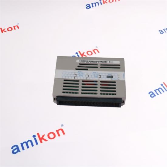
Part Number |
1C31192G01 |
|
Brand |
WESTINGHOUSE |
|
Condition |
Brand New |
|
dimension |
12x2.8x9.4cm |
|
Weight |
0.12kg |
Company Service
l Rich experience (Over 20 years of sales experience)
l Fast delivery (In-stock products usually ship within 1-3 days)
l Large inventory (Carrying various brands and maintaining overseas warehouses)
l Quality assurance (Products come with a 1-year warranty)
|
Contact us |
||
|
Maneger |
|
Telephone |
|
Miya zheng |
||
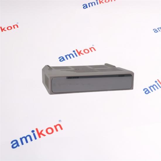
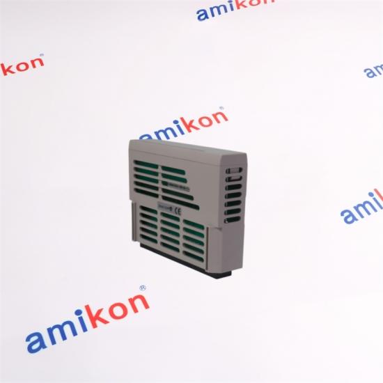
Descripution
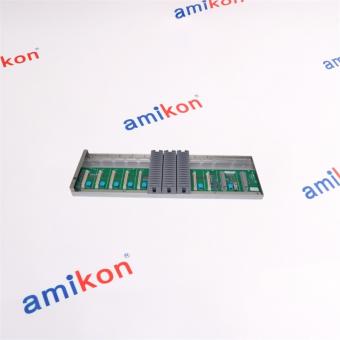
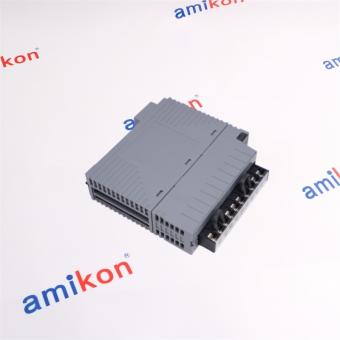
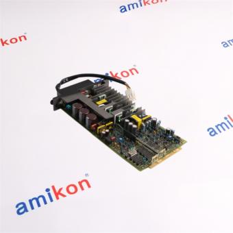
1C31192G01 is one Personality module group for the Speed Detector Module
The Speed Detector Module determines the speed of a piece of equipment by measuring the frequency of the output signal from a tachometer. The tachometer output can be sinusoidal or a pulse train. The Speed Detector provides a 16-bit output at an update rate of 5 milliseconds for over-speed detection, and a 32-bit output at a variable update rate for speed regulation.
Specifications
|
Number of Channels |
1 |
|
Dielectric Isolation (Field Circuit to Logic Common) |
1000 VAC/DC |
|
Maximum Input Withstand Voltage |
140 VAC RMS or 150 VDC |
|
Maximum Usable Input Voltage |
200 V Peak-to-Peak |
|
Maximum Off-State Input Voltage |
0.2 V Peak-to-Peak |
|
Input Duty Cycle |
Minimum: 20%Maximum: 80% |
|
Maximum Input DC Offset |
150 VDC − 0.5 × Maximum Input Voltage (Peak-to-Peak) |
|
Normal Mode Rejection |
Maximum 140 VAC or 150 VDC |
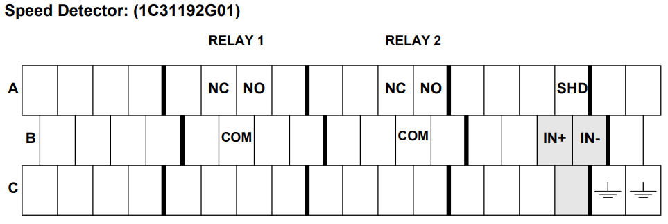
Speed Detector Terminal Block Wiring Information
Speed Detector Terminal Block Wiring Information Each Personality module has a simplified wiring diagram label on its side, which appears above the terminal block. This diagram indicates how the wiring from the field is to be connected to the terminal block in the base unit. The diagram for the Speed Detector Personality module is illustrated in Figure. The following table lists and defines the abbreviations used in this diagram.
|
Abbreviation |
Definition |
|
COM |
Common terminal of relay’s contact. |
|
⏚ (Earth Ground) |
Earth ground terminals used to connect to the input signal shield (see field connection diagram for wiring details). |
|
IN+, IN- |
Positive and negative terminal connections of the input signal. |
|
NC |
Normally closed terminal of relay’s contact. |
|
NO |
Normally open terminal of relay’s contact. |
|
SHD |
Shield of input signal’s cable (see Figure 24-2 for field connection.) |
|
|
|
FAQ
1. Question: How does the 1C31192G01 architecture ensure deterministic signal processing performance under high-load industrial automation conditions, and what core design principles govern its operational precision?
Answer: The 1C31192G01 is typically engineered with high-reliability signal handling pathways that ensure deterministic response and low-latency processing. Its precision performance is achieved through controlled circuit isolation, optimized signal routing design, and the use of industrial-grade electronic components suitable for continuous operation in automation systems.
2. Question: What advanced diagnostic intelligence mechanisms are integrated into the 1C31192G01 to facilitate real-time system health monitoring and anomaly detection in distributed control environments?
Answer: The 1C31192G01 generally integrates embedded diagnostic functions and status monitoring capabilities that continuously evaluate system behavior. These mechanisms enable early anomaly detection, support predictive maintenance strategies, and reduce unexpected downtime in distributed control applications.
3. Question: In what manner does the 1C31192G01 maintain interoperability across heterogeneous PLC and DCS ecosystems, and what interface standardization strategies are typically employed to ensure seamless integration?
Answer: The 1C31192G01 is designed with standardized industrial interface architecture that enables compatibility across multiple PLC and DCS platforms. Its modular connectivity approach ensures stable data exchange and smooth integration within both legacy and modern automation infrastructures.
4. Question: How does the 1C31192G01 implement electromagnetic interference suppression and signal conditioning techniques to sustain performance integrity in electrically noisy industrial environments?
Answer: The 1C31192G01 incorporates EMC-oriented design techniques such as multi-layer grounding, signal isolation structures, and integrated filtering components. These features effectively suppress electromagnetic interference and maintain high signal integrity in harsh industrial environments.
5. Question: What lifecycle engineering and thermal resilience strategies are embedded in the 1C31192G01, and how do they contribute to long-term operational reliability in continuous process control applications?
Answer: The 1C31192G01 is built with extended lifecycle engineering principles and industrial-grade thermal management design. Its optimized heat dissipation structure and high-temperature-tolerant components ensure stable long-term performance in 24/7 continuous industrial operations.
More items
|
PR6426/010-030 CON021 |
PR6426/010-000 CON021 |
PR6423/103-141 CON041 |
|
PR6423/004-010 |
MMS6823 |
PR6423/105-141 CON041 |
|
PR6423/000-131-CN CON031 |
PR6423/000-031 CON041 |
PR6424/104-141 CON041 |
|
PR6423/004-120-CN CON021 |
PR6423/013-130 CON021 |
PR6423/106-OF1 PR6423/106-0F1 |
|
PR6423/002-001-CN CON041 |
PR6423/019-040 CON021 |
PR6424/010-110 CON021 |
|
PR6423/010-100-CN CON021 |
PR6426/000-121 CON031 |
PR6423/004-030 CON021 |
|
PR6426/000-040 CON021 |
PR9350/12 |
PR6423/018-010 CON021 |
|
PR6423/011-131 CON031 |
PR6423/100-141 CON041 |
PR6424/010-010-CN CON021 |

Embrace the Future of Innovation Unlock the Power of Seamless Automation By integrating advanced automation solutions, real-time analytics, sophisticated control systems, and lifecycle services, improves operational performance while reducing risks, costs, and downtime. WeChat: hu18030235311 | WhatsApp: +86-18030235311 Mobile: +86-18030235311 | E-mail: sales3@amikon.cn

Embrace the Future of Innovation Unlock the Power of Seamless Automation By integrating advanced automation solutions, real-time analytics, sophisticated control systems, and lifecycle services, improves operational performance while reducing risks, costs, and downtime. WeChat: hu18030235311 | WhatsApp: +86-18030235311 Mobile: +86-18030235311 | E-mail: sales3@amikon.cn

Embrace the Future of Innovation Unlock the Power of Seamless Automation By integrating advanced automation solutions, real-time analytics, sophisticated control systems, and lifecycle services, improves operational performance while reducing risks, costs, and downtime. WeChat: hu18030235311 | WhatsApp: +86-18030235311 Mobile: +86-18030235311 | E-mail: sales3@amikon.cn

Embrace the Future of Innovation Unlock the Power of Seamless Automation By integrating advanced automation solutions, real-time analytics, sophisticated control systems, and lifecycle services, improves operational performance while reducing risks, costs, and downtime. WeChat: hu18030235311 | WhatsApp: +86-18030235311 Mobile: +86-18030235311 | E-mail: sales3@amikon.cn

Embrace the Future of Innovation Unlock the Power of Seamless Automation By integrating advanced automation solutions, real-time analytics, sophisticated control systems, and lifecycle services, improves operational performance while reducing risks, costs, and downtime. WeChat: hu18030235311 | WhatsApp: +86-18030235311 Mobile: +86-18030235311 | E-mail: sales3@amikon.cn

Embrace the Future of Innovation Unlock the Power of Seamless Automation By integrating advanced automation solutions, real-time analytics, sophisticated control systems, and lifecycle services, improves operational performance while reducing risks, costs, and downtime. WeChat: hu18030235311 | WhatsApp: +86-18030235311 Mobile: +86-18030235311 | E-mail: sales3@amikon.cn

Embrace the Future of Innovation Unlock the Power of Seamless Automation By integrating advanced automation solutions, real-time analytics, sophisticated control systems, and lifecycle services, improves operational performance while reducing risks, costs, and downtime. WeChat: hu18030235311 | WhatsApp: +86-18030235311 Mobile: +86-18030235311 | E-mail: sales3@amikon.cn

Embrace the Future of Innovation Unlock the Power of Seamless Automation By integrating advanced automation solutions, real-time analytics, sophisticated control systems, and lifecycle services, improves operational performance while reducing risks, costs, and downtime. WeChat: hu18030235311 | WhatsApp: +86-18030235311 Mobile: +86-18030235311 | E-mail: sales3@amikon.cn


Inventory Products


More than 40.000.000 products available and worldwide support


 Trust Guaranteed
 Customer Support


 IPv6 network supported